
User's Manual


SYSTEM DESCRIPTION AND INSTALLATION MANUAL
T
3
CAS/Part No.9005000
Table 1-19: Thales VSI-TCAS Leading Particulars
Item
Specification
Dimensions (maximum)
● Height 3.26 in. (82.8 mm)
● Width 3.26 in. (82.8 mm)
●
Length
7.5 in. (190.0 mm)
Weight (maximum)
3.3 lb (1.5 kg)
Power Requirements:
●
Primary
115 V, 400 Hz; 17 W nominal (Day),
12 W nominal (Night),
20 W maximum
● External Circuit Breaker Rating 1 A at 115 V ac
Display Type
LCD
Mating Connectors:
● J1 (41 Pin)
M83723/75A-20-41-6
M83723/75A-20-41-N
●
Pneumatic Fitting
MS33649-5
●
Quick Disconnect (Hardware p/n KB &PB
only)
40006-1B45
●
Packing
MS9385-05
Mounting
3-ATI Clamp, Marmon NH1004994-30
or MSP 64311B
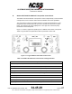
(1) Functional Description and Operation
The VSI/TRA has three functions. It continuously displays rate of climb or rate of
descent. Traffic information is displayed and resolution advisory information is
displayed against vertical speed to allow the flight crew to avoid threats.
The vertical speed display is generated from signals applied directly to the
indicator. The VSI/TRA is designed to be used in place of a conventional vertical
speed indicator. Four possible sources exist for vertical speed data including
ARINC 429 data, dc analog signals in accordance with ARINC 575
(approximately 500 millivolts per 1000 feet per minute or per 304.8 meters per
minute), ac analog signals in accordance with ARINC 565 (approximately 250
millivolts per 1000 feet per minute or 304.8 meters per minute), and ARINC 429
signals from the ACSS Pressure Transducer Module. The VSI/TRA computes
vertical rate from electrical static pressure when a remote static sensor is used.
These four program pin selectable configurations provide compatibility with most
aircraft.
Pub. No. 8600200-001, Revision 004
34-45-29
1-70
04 Nov 2014
Use or disclosure of information on this page is subject to the restrictions in the proprietary notice of this document.