AET65 Smart Card Reader Reference Manual info@acs.com.hk Subject to change without prior notice www.acs.com.
Table of Contents 1.0. Introduction ............................................................................................................... 4 2.0. AET65 Smart Card Reader ....................................................................................... 5 3.0. Features ..................................................................................................................... 6 4.0. Smart Card Support ..............................................................................
Tables Table 1. USB Interface Wiring .......................................................................................................... 10 Page 3 of 19 AET65 Reference Manual Document Title Here Version 1.00 Document Title Here info@acs.com.hk www.acs.com.
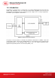
1.0. Introduction The AET65 is a composite device, consisting of the core of ACS’ ACR38-SAM smart card reader and UPEK’s swipe fingerprint sensor. The smart card reader and the fingerprint sensor can be used independently, but combining the two technologies provide a higher level of security in applications. The AET65’s system diagram is shown below: Figure 1.
2.0. AET65 Smart Card Reader The AET65 Smart Card Reader acts as an interface for the communication between a computer (for example, a PC) and a smart card. Different types of smart cards have different commands and different communication protocols which prevents, in most cases the direct communication between a smart card and a computer. The AET65 Smart Card Reader is based on the ACR38-SAM core which establishes a uniform interface from the computer to the smart card for a wide variety of cards.
3.0. Features The following are the features of the AET65 Smart Card Reader: 1. PS/SC 2. WHQL Certified Drivers 3. CE and FCC 4. RoHS 5. ISO 7816 (Class A, B, C) 6. MCU Card Support (T=0, T=1) 7. USB Full-Speed 8. Short Circuit Protection Page 6 of 19 AET65 Reference Manual Document Title Here Version 1.00 Document Title Here info@acs.com.hk www.acs.com.
4.0. Smart Card Support 4.1. MCU Cards The AET65 Smart Card Reader is a PC/SC compliant smart card reader that supports ISO 7816 5 V, 3 V and 1.8 V (Class A, B, and C) smart cards. The AET65 also works with MCU cards following either the T=0 and T=1 protocol. Page 7 of 19 AET65 Reference Manual Document Title Here Version 1.00 Document Title Here info@acs.com.hk www.acs.com.
5.0. Smart Card Interface The interface between the AET65 and the inserted smart card follows the specifications of ISO7816-3 with certain restrictions or enhancements to increase the practical functionality of the AET65. 5.1. Smart Card Power Supply VCC (C1) The current consumption of the inserted card must not be higher than 50 mA. 5.2. Programming Voltage VPP (C6) According to ISO 7816-3, the smart card contact C6 (VPP) supplies the programming voltage to the smart card.
6.0. Power Supply The AET65 requires a voltage of 5 V DC, 100 mA regulated power supply. The AET65 Smart Card Reader gets power supply from a PC (through the cable supplied along with each type of reader). 6.1. Status LED The Green LED around the card slot indicates the activation status of the smart card interface: ON Indicates that the power supply to the smart card is switched on, i.e., the smart card is activated. OFF Indicates that the power supply to the smart card is switched off, i.e.
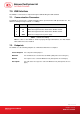
7.0. USB Interface The AET65 is connected to a computer through a USB following the USB standard. 7.1. Communication Parameters The AET65 is connected to a computer through USB as specified in the USB Specification 2.0. The AET65 is working in full speed mode, i.e. 12 Mbps. Pin Signal Function 1 V BUS 2 D- Differential signal transmits data between AET65 and PC. 3 D+ Differential signal transmits data between AET65 and PC.
8.0. Communication Protocol 8.1. AET65 Communication Protocol During normal operation, the AET65 acts as a slave device with regard to the communication between a computer and the reader. The communication is carried out in the form of successive commandresponse exchanges. The computer transmits a command to the reader and receives a response from the reader after the command has been executed. A new command can be transmitted to the AET65 only after the response to the previous command has been received.
00H = command successfully executed Otherwise = error in command data, or command cannot be executed A table listing the possible values of the status byte and the corresponding meaning is given in Appendix B.2. Data Length Number of subsequent data bytes, and is encoded in 2 bytes. The first byte (MSB) and second byte (LSB) represent data length N. Data Data contents of the command.
9.0. AET65 Commands The commands executed by the AET65 can generally be divided into two categories, namely, Control Commands and Card Commands. Control Commands are in charge of the internal operation of the AET65. They do not directly affect the card inserted in the reader and are therefore independent of the selected card type. Card Commands are directed toward the card inserted in the AET65.
01H: card inserted, not powered up 03H: card powered up 9.1.2. SELECT_CARD_TYPE This command sets the required card type. The firmware in the AET65 adjusts the communication protocol between reader and the inserted card according to the selected card type. Command format Header Instruction Data length Data LEN 01 H 02 H TYPE 00 H TYPE 01 H See Appendix B.1 for the value to be specified in this command for a particular card to be used.
9.1.4. SET_CARD_PPS This command sends PPS Request to the smart card. SET_READER_PPS. This command should work in pair with Command format Header Instruction 01 H 0A H LEN Data length Data LEN PPS Request MSB LSB Length of PPS request.
9.2. MCU Card Commands 9.2.1. RESET_WITH_5_VOLTS_DEFAULT This command powers up the card inserted in the card reader and performs a card reset. If the card is powered up when the command is being issued, only a reset of the card is carried out. The power supply to the card is not switched off.
9.2.3. POWER_OFF This command powers off the card inserted in the card reader. Command format Header Instruction Data length LEN 01 H 81 H 00 H 00 H Response data format Header Status Data length LEN 01 H 9.2.4. EXCHANGE_TPDU_T0 To exchange an APDU (Application Protocol Data Unit) command/response pair, between the MCU card inserted in the AET65 and the host computer.
9.2.5. EXCHANGE_TPDU_T1 To exchange an APDU (Application Protocol Data Unit) command/response pair, between the MCU card inserted in the AET65 and the host computer using T1 protocol. Command format Header Instruction Data length LEN MSB 01 H A1 H MSB Data LSB T1 TPDU Frame ……… LSB LEN Length of APDU command data, N Data T1 TPDU frame to be sent to the card. It should include NAD, PCB, LEN, INF and EDC fields. Please refer to ISO/IEC 7816:3:1997(E) Section 9.4 for detailed information.
Appendix A. AET65 Appendix A.1. Supported Card Types The following table shows the values that must be specified in the SET_CARD_TYPE command for a particular card type to be used, and how the bits in the response to the GET_ACR_STAT command correspond with the respective card types. Card Type Card Type 00 H Auto-select T=0 or T=1 communication protocol 0C H MCU-based cards with T=0 communication protocol 0D H MCU-based cards with T=1 communication protocol Appendix A.2.