
User Manual
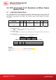

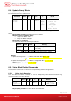
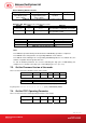

Data In: Blinking Duration Control
Byte 0 Byte 1 Byte 2 Byte 3
T1 Duration
Initial Blinking State
(Unit = 100ms)
T2 Duration
Toggle Blinking State
(Unit = 100ms)
Number of
repetition
0x00
Table 34: Bi-Color LED Blinking Duration Control Format (4 Bytes)
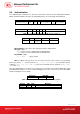
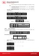
Data Out: SW1 SW2. Status Code returned by the reader.
Results SW1 SW2 Meaning
Success 90
Current LED
State
The operation is completed successfully.
Error
63 00
The operation is failed.
Table 35: Status Code
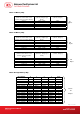
Status Item Description
Bit 0 Current Red LED 1 = On; 0 = Off
Bit 1 Current Green LED 1 = On; 0 = Off
Bits 2 – 7 Reserved
Table 36: Current LED State (1 Byte)
Note:
The LED State operation will be performed after the LED Blinking operation is completed.
The LED will not be changed if the corresponding LED Mask is not enabled.
The LED will not be blinking if the corresponding LED Blinking Mask is not enabled. Also, the
number of repetition must be greater than zero.
T1 and T2 duration parameters are used for controlling the duty cycle of LED blinking. For
example, if T1=1 and T2=1, the duty cycle = 50%. #Duty Cycle = T1 / (T1 + T2).
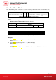
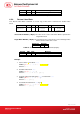
7.3. Get the Firmware Version of the reader
This is used to retrieve the firmware version of the reader.
Command Class INS P1 P2 Le
Get
Response
0xFF 0x00 0x48 0x00 0x00
Table 37: Command Format (5 Bytes)
Response Data Out
Result Firmware Version
Table 38: Response Format (10 bytes)
E.g. Response = 41 45 54 36 32 30 33 30 30 (Hex) = AET620300 (ASCII)
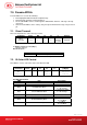
7.4. Get the PICC Operating Parameter
This is used to retrieve the PICC Operating Parameter of the reader.
Command
Class INS P1 P2 Le
Get
Response
0xFF 0x00 0x50 0x00 0x00
Table 39: Command Format (5 Bytes)
Document Title Here
Document Title Here
Document Title Here
AET62 Reference Manual
Version 1.00
Page 20 of 35
info@acs.com.hk
www.acs.com.hk