AET62 NFC Reader Reference Manual info@acs.com.hk Subject to change without prior notice www.acs.com.
Table of Contents 1.0. Introduction ............................................................................................................... 5 2.0. AET62 Contactless Smart Card Reader .................................................................. 6 2.1. USB Interface ........................................................................................................................6 3.0. Implementation ....................................................................................
Figures Figure 1: AET62 System Block Diagram .......................................................................................... 5 Figure 2: Communication Flow Chart of AET62 ............................................................................... 7 Figure 3: Basic Program Flow for Contactless Applications........................................................... 22 Tables Table 1: USB Interface ...........................................................................................
Table 34: Bi-Color LED Blinking Duration Control Format (4 Bytes) .............................................. 20 Table 35: Status Code ..................................................................................................................... 20 Table 36: Current LED State (1 Byte) ............................................................................................. 20 Table 37: Command Format (5 Bytes) .............................................................................
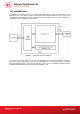
1.0. Introduction The AET62 is a composite device, consisting ACS’ ACR122U NFC Reader’s core and UPEK’s swipe fingerprint sensor. The NFC contactless smart card reader and the fingerprint sensor can be used independently, but combining the two technologies provide a higher level of security in applications.
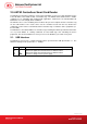
2.0. AET62 Contactless Smart Card Reader The AET62 is a PC-linked contactless smart card reader/writer used for accessing ISO14443-4 Type A and B, Mifare, ISO 18092 or NFC, and FeliCa tags. The AET62 Smart Card Reader is PCSCcompliant so it is compatible with existing PCSC applications. Furthermore, the standard Microsoft CCID driver is used to simplify driver installation. The AET62 serves as the mediating device between the personal computer and the contactless tag via the USB interface.
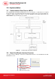
3.0. Implementation 3.1. Communication Flow Chart of AET62 The Standard Microsoft CCID and PCSC drivers are used. Therefore, no ACS drivers are required because the drivers are already built inside the windows operating system. You need to modify your computer’s registry settings to be able to use the full capabilities of the AET62 NFC Reader. See AET62 PCSC Escape Command for more details. Figure 2: Communication Flow Chart of AET62 3.2.
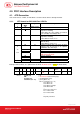
4.0. PICC Interface Description 4.1. ATR Generation If the reader detects a PICC, an ATR will be sent to the PCSC driver to identify the PICC. 4.1.1. ATR format for ISO 14443 Part 3 PICCs Byte 0 Value (Hex) 3B Designation Initial Header 1 8N T0 2 80 3 01 80 4 To 4F 0C RID 3+N SS C0 .. C1 00 00 00 00 UU Table 2: 4+N Description Higher nibble 8 means: no TA1, TB1, TC1 only TD1 is following.
4.1.2. ATR format for ISO 14443 Part 4 PICCs Byte 0 Value (Hex) 3B Designation Initial Header 1 8N T0 2 80 TD1 3 01 TD2 4 to 3+N XX XX XX XX T1 Tk Description Higher nibble 8 means: no TA1, TB1, TC1 only TD1 is following. Lower nibble N is the number of historical bytes (HistByte 0 to HistByte N-1) Higher nibble 8 means: no TA2, TB2, TC2 only TD2 is following. Lower nibble 0 means T = 0 Higher nibble 0 means no TA3, TB3, TC3, TD3 following.
5.0. PICC Commands for General Purposes 5.1. Get Data The “Get Data command” will return the serial number or ATS of the “connected PICC”.
6.0. PICC Commands (T=CL Emulation) for Mifare Classic Memory Cards 6.1. Load Authentication Keys The “Load Authentication Keys command” will load the authentication keys into the reader. The authentication keys are used to authenticate the particular sector of the Mifare 1K/4K Memory Card. Two kinds of authentication key locations are provided, volatile and non-volatile key locations respectively.
6.2. Authentication The “Authentication command” uses the keys stored in the reader to execute authentication with the Mifare 1K/4K card (PICC). Two types of authentication keys are used: TYPE_A and TYPE_B.
Mifare 1K Memory Map. Data Blocks (3 blocks, 16 bytes per block) 0x00 ~ 0x02 0x04 ~ 0x06 Trailer Block (1 block, 16 bytes) 0x38 ~ 0x0A 0x3C ~ 0x3E 0x3B 0x3F Sectors (Total 32 sectors. Each sector consists of 4 consecutive blocks) Sector 0 Sector 1 .. .. Sector 30 Sector 31 Data Blocks (3 blocks, 16 bytes per block) 0x00 ~ 0x02 0x04 ~ 0x06 Trailer Block (1 block, 16 bytes) 0x78 ~ 0x7A 0x7C ~ 0x7E 0x7B 0x7F Sectors (Total 8 sectors. Each sector consists of 16 consecutive blocks) Sector 32 Sector 33 .
Example: 1. To authenticate the Block 0x04 with a {TYPE A, key number 0x00}. For PC/SC V2.01, Obsolete. APDU = {FF 88 00 04 60 00}; 2. To authenticate the Block 0x04 with a {TYPE A, key number 0x00}. For PC/SC V2.07 alaAPDU = {FF 86 00 00 05 01 00 04 60 00} Note: Mifare Ultralight does not need to execute any authentication. The memory is free to access. Page 14 of 35 AET62 Reference Manual Document Title Here Version 1.00 Document Title Here info@acs.com.hk www.acs.com.
6.3. Read Binary Blocks The “Read Binary Blocks command” is used for retrieving “data blocks” from the PICC. The data block/trailer block must be authenticated first.
6.4. Update Binary Blocks The “Update Binary Blocks command” is used for writing “data blocks” into the PICC. The data block/trailer block must be authenticated. Command Update Binary Blocks Class INS P1 P2 Lc Data In FF D6 00 Block Number Number of Bytes to Update Block Data 4 Bytes for Mifare Ultralight or 16 Bytes for Mifare 1K/4K Table 19: Update Binary APDU Format (4 or 16 + 5 Bytes) where: Block Number (1 Byte):The starting block to be updated.
0x00 = Store the VB_Value into the block. The block will then be converted to a value block. 0x01 = Increment the value of the value block by the VB_Value. This command is only valid for value block. 0x02 = Decrement the value of the value block by the VB_Value. This command is only valid for value block. VB_Value (4 Bytes): The value used for value manipulation. The value is a signed long integer (4 bytes).
Results Success Error 6.5.3. SW1 SW2 Meaning 90 00 The operation is completed successfully. 63 00 The operation is failed. Table 26: Read Value Block Response Codes Restore Value Block The “Restore Value Block command” is used to copy a value from a value block to another value block.
7.0. Pseudo-APDUs Pseudo-APDUs are used for the following: Exchanging Data with Non-PCSC Compliant Tags. Retrieving and setting the reader parameters. The Pseudo-APDUs can be sent through the “AET62 PICC Interface” if the tag is already connected. Or the Pseudo-APDUs can be sent by using “Escape Command” if the tag is not presented yet. 7.1. Direct Transmit This is the Payload to be sent to the tag or reader.
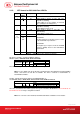
Data In: Blinking Duration Control Byte 0 Byte 1 Byte 2 Byte 3 T1 Duration T2 Duration Number of 0x00 Initial Blinking State Toggle Blinking State repetition (Unit = 100ms) (Unit = 100ms) Table 34: Bi-Color LED Blinking Duration Control Format (4 Bytes) Data Out: SW1 SW2. Status Code returned by the reader. Results SW1 SW2 Meaning Current LED Success 90 The operation is completed successfully. State Error 63 00 The operation is failed.
Response Result Data Out PICC Operating Parameter Table 40: Response Format (1 byte) 7.5. Set the PICC Operating Parameter This is used to set the PICC Operating Parameter of the reader.
8.0. Basic Program Flow for Contactless Applications Step 0. Start the application. The reader will do the PICC Polling and scan for tags continuously. Once the tag is found and detected, the corresponding ATR will be sent to the PC. You must make sure that the PCSC Escape Command has been set. See AET62 PCSC Escape Command for more details. Step 1. The first thing is to connect the “AET62 PICC Interface”. Step 2. Access the PICC by sending APDU commands. : : Step N. Disconnect the “AET62 PICC Interface”.
8.1. How to Access PCSC-Compliant Tags (ISO 14443-4)? Basically, all ISO 14443-4 compliant cards (PICCs) would understand the ISO 7816-4 APDUs. The AET62 Reader just has to communicate with the ISO 14443-4 compliant cards through exchanging ISO 7816-4 APDUs and Responses. AET62 will handle the ISO 14443 Parts 1-4 Protocols internally. Mifare 1K, 4K, MINI and Ultralight tags are supported through the T=CL emulation. Just simply treat the Mifare tags as standard ISO 14443-4 tags.
8.2. How to Access DESFire Tags (ISO 14443-4)? DESFire supports ISO 7816-4 APDU Wrapping and Native modes. Once the DESFire Tag is activated, the first APDU sent to the DESFire Tag will determine the “Command Mode”. If the first APDU is in “Native Mode”, the rest of the APDUs must be in “Native Mode” format. Similarly, if the first APDU is in “ISO 7816-4 APDU Wrapping Mode”, the rest of the APDUs must be in “ISO 7816-4 APDU Wrapping Mode” format.
8.3. How to Access FeliCa Tags (ISO 18092)? Typical sequence may be: - Present the FeliCa Tag and Connect the PICC Interface Read / Update the memory of the tag Step 1) Connect the Tag The ATR = 3B 8F 80 01 80 4F 0C A0 00 00 03 06 03 F0 11 00 00 00 00 8A In which, F0 11 = FeliCa 212K Step 2) Read the memory block without using Pseudo APDU.
Tip: To read all the memory content of the tag << 00 >> 11 48 18 26 .. 00 [90 00] Step 3) Update the memory address 08(Block 1: Byte-0)with the data FF << 53 08 FF >> FF [90 00] In which, Response Data = FF Topaz Memory Map. Memory Address = Block No * 8 + Byte No e.g. Memory Address 08 (hex) = 1 x 8 + 0 = Block 1: Byte-0 = Data0 e.g. Memory Address 10 (hex) = 2 x 8 + 0 = Block 2: Byte-0 = Data8 Please refer to the Jewel and Topaz specifications documents for more detailed information.
8.5. Get the Current Setting of the Contactless Interface Step 1) Get Status Command << FF 00 00 00 02 D4 04 >> D5 05 [Err] [Field] [NbTg] [Tg] [BrRx] [BrTx] [Type] 80 90 00 Or if no tag is in the field >> D5 05 00 00 00 80 90 00 [Err] is an error code corresponding to the latest error detected. Field indicates if an external RF field is present and detected (Field = 0x01) or not (Field = 0x00). [NbTg] is the number of targets. The default value is 1.
Appendix A. AET62 PCSC Escape Command 1. Select the “ACS AET62 PICC Interface 0” 2. Select the “Shared Mode” if the “AET62 PICC Interface” is already connected or “Direct Mode if the “AET62 PICC Interface” is not connected. 3. Press the “Connect” button to establish a connection between the PC and the AET62 reader. 4. Enter “3500” in the Command text box 5. Enter the PCSC Escape Command, e.g. “FF 00 48 00 00” and press the “Send” button to send the command to the reader. #Get the firmware version 6.
Add a DWORD “EscapeCommandEnable” under HKLM\SYSTEM\CCS\Enum\USB\Vid_072F&Pid_0 102\Device Parameters For Vista, the path is: Computer\HKEY_LOCAL_MACHINE\SYSTEMS\C urrentControlSet\Enum\USB Look for: VID_072F&PID_0102 Then expand the node. Look under Device parameters Create a DWORD entry (32-bit) with the name: EscapeCommandEnable Page 29 of 35 AET62 Reference Manual Document Title Here Version 1.00 Document Title Here info@acs.com.hk www.acs.com.
To Modify the value of the EscapeCommandEnable double click on the entry and input 1 in the Value data with the base set in Hexadecimal. Page 30 of 35 AET62 Reference Manual Document Title Here Version 1.00 Document Title Here info@acs.com.hk www.acs.com.
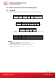
Appendix B. APDU Command and Response Flow for ISO 14443-Compliant Tags Assume an ISO14443-4 Type B tag is used. << Typical APDU Command and Response Flow >> PC Reader Tag Sequences USB Interface RF Interface (12Mbps) (13.56MHz) Contactless Related Command Tag-specific Command Frame [APDU Command] [APDU Command] embedded in ISO14443 Frame 1. The command is sent e.g. [00 84 00 00 08] (Get Challenge) 2.
Appendix C. APDU Command and Response Flow for ISO 18092-Compliant Tags Assume a TOPAZ tag is used. << Typical APDU Command and Response Flow >> PC Reader Tag Sequences USB Interface RF Interface (12Mbps) (13.56MHz) Contactless Related Command Tag-specific Command Frame 1. The command is sent [Native Command] e.g. [01 08] (read memory address 08) [Native Command] embedded in ISO18092 Frame or Pseudo APDU Command + [Native Command] e.g. FF 00 00 00 05 D4 40 01 [01 08] 2.
Appendix D.
Appendix E. Sample Codes for Setting the LED Example 1: To read the existing LED State // Assume both Red and Green LEDs are OFF initially // APDU = “FF 00 40 00 04 00 00 00 00” Response = “90 00”. RED and Green LEDs are OFF. Example 2: To turn on RED and Green Color LEDs // Assume both Red and Green LEDs are OFF initially // APDU = “FF 00 40 0F 04 00 00 00 00” Response = “90 03”.
Example 4: To turn on the Red LED for 2 sec. After that, resume to the initial state // Assume the Red LED is initially OFF, while the Green LED is initially ON. // // The Red LED will turn on during the T1 duration, while the Green LED will turn off during the T1 duration.
Example 6: To blink the Red and Green LEDs of 1Hz for 3 times // Assume both the Red and Green LEDs are initially OFF.