
Instruction Manual


AR-V5430FL Installation Guide
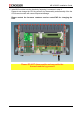
Connectors and Jumper Setting
23/39
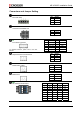
PWR1
DC Power Input
PIN SIGNAL
1 DC_IN
2 Key switch
3 GND
FUSE1
Connect to fuse default 15A
PIN SIGNAL
1,2 Fuse Out
3,4 Fuse In
J4
Front Panel connector
For detailed functions, please refer to the User
Manual.
PIN SIGNAL PIN SIGNAL
1
PWRBTN_IN 2 GND
3
LOC_SW 4 GND
5
KEY_SW 6 GND
7
ENG_STS 8 GND
9
STS_LED 10 GND
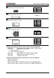
PWR3
Suspend Power for ATX function
PIN SIGNAL
1 GND
2 PS_ON
3 5V_SUS
CN1
Power button output
PIN SIGNAL
1 PWBTN out
2 GND
CN2
Reserve Pin
PIN SIGNAL
1 PWBTN out
2 GND
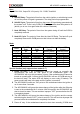
SW1
DIP switch for mode select.
Mode 1 2 3 4
0 ON ON ON ON
1 ON ON ON OFF
2 ON ON OFF ON
3 ON ON OFF OFF
4 ON OFF ON ON
5 ON OFF ON OFF
6 ON OFF OFF ON
7 ON OFF OFF OFF