Revision: 1.0 AR-V5403FL Installation Guide Revision 1.
Revision: 1.0 Contents 1 Introduction to AR-V5403FL.....................................................3 1.1 1.2 Specifications ................................................................................ 3 Packing List ................................................................................... 3 2 Procedure of Assembly/Disassembly .....................................8 2.1 2.2 2.3 2.5” Hard Disk Installation ............................................................
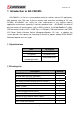
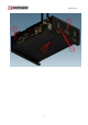
Revision: 1.0 1 Introduction to AR-V5403FL AR-V5403FL is a Fan-less system product mainly for vehicles industry PC applications. With powerful Intel CPU core & diverse memory card extension (according to CF card, SO-DIM), AR-V5403FL can satisfy the users requirements in any vehicles industry applications environment, especially in vehicles computer fields.
Revision: 1.
Revision: 1.
Revision: 1.
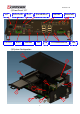
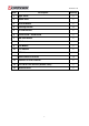
Revision: 1.0 Item Description Quantity 1 Upper Cover 1 2 Bottom Case 1 3 Thermal Module 1 4 Mounting Bracket 2 5 CF Card Bracket 1 6 Mother board + GPIO board 1 7 HDD/SSD Module 1 8 GPS Module 1 9 3.5G Module 1 10 Wi-Fi Module 1 11 DDRII Lid 1 12 Hook modules of bracket 4 13 Antennas of GPS/3.
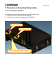
Revision: 1.0 2 Procedure of Assembly/Disassembly 2.1 2.5” Hard Disk Installation The following instructions will guide you to install HDD step-by-step: 1. Remove the terminal plug from the AR-V5403FL. 2. Unfasten the screws from storage plate of AR-V5403FL.
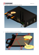
Revision: 1.0 3. Pulled the storage plate by below photo direction. Pulled 4. Inserted the storage device into the HDD plater. Caution! Check the Direction is correct. Install the storage device on the HDD plater with four Push it! Install the storage device.
Revision: 1.0 5. 6. Place HDD module back into the case. Fix HDD module to the chassis by two screws. Push!! Put HDD module back into the chassis.
Revision: 1.0 7. Slide the top cover into or take off the bottom chassis.
Revision: 1.0 8. Finish the modules (3.5G/GPS/Wifi-Bluetooth) installation after fastening the screw.
Revision: 1.0 2.2 Accessory (CF card, 3.5G, GPS, Wi-Fi Bluetooth, SIM Card, Outline bracket) Installation z Install CF Card 1. Remove the extending CF’s bracket by unfastening the screws. Unfasten the screws 2. Install CF card into bracket. Install CF card by the following direction.
Revision: 1.0 3. Install CF card module back to CF socket. Caution!! The snapping side is downward. Install the CF card module into CF slot. z Install SIM Card Install SIM card into the SIM socket.
Revision: 1.0 z 1. 2. 3. Install Outline Bracket Install fasteners with case by 4 screws. Install fasteners’ another side with Outline bracket by 4 screws. Lock the fasteners. Fixed each pins, by the following direction.
Revision: 1.0 2.3 GPS/3.5G/WiFi-Bluetooth Modules Installation 1. Unfasten 2 screws to release Wi-Fi Bluetooth bracket. Unfasten the screws.
Revision: 1.0 2. Install GPS/3.5G modules into chassis by fastening screws. Install 3.5G modules into chassis by fastening 2 screws. Install GPS modules into chassis by fastening 4screws.
Revision: 1.0 3 Appendix Please do not change CPU by yourself. Any disassembly and assembly behavior for the CPU thermal module will causes unexpected damages. Contact with Acrosser customer service center/FAE to change CPU.
Revision: 1.
Revision: 1.0 4 Introductions of AR-B5403 Welcome to the AR-B5403 Computer. The AR-B5403 is an Intel Core 2 Duo EPIC single board computer provides variety of display outputs. In addition to VGA, DVI and LVDS display outputs, AR-B5403 supports S-Video, BNC, and component TV outputs. 4.
Revision: 1.0 SATA 2 x SATA II port, CF 1 x External Compact Flash Type I/II socket Disk Bay 1 x Anti-shock 2.5" HDD bracket swappable without open case I/O Ethernet 2 x Gbps RJ45 with LED, Broadcom BCM5787 Serial Port 4 x RS-232 (2 x DB9, 2 x pin header, COM3 for reserve for PIC on power circuit, COM4 for GPS USB 7 x USB2.
Revision: 1.0 z Remote switch(audio jack) z System status LED(blue) z Embedded power local switch AR-PW0932V default is Mode 2 Mechanical & Environment Thermal Design Heat pipe solution Chassis Material Metal steel Bracket Bracket with anti-thief function (Locker option) Dimension T.B.D. Vibration IEC 60068-2-64 5~500Hz, 3GRMS for SSD/CF, 1GRMS for 2.5”HDD, operating Shock IEC 60068-2-27 50G-500m/s -11ms, operating Operating Temp. -15~50℃ with Industrial Grade CF or SSD Storage Temp.
Revision: 1.0 4.
Revision: 1.0 5 Hardware’s Information This chapter describes the installation of AR-B5403. At first, it shows the Function diagram and the layout of AR-B5403. It then describes the unpacking information which you should read carefully, as well as the jumper/switch settings for the AR-B5403 configuration. 5.1 Locations 5.1.
Revision: 1.0 5.1.
Revision: 1.0 5.1.3 Connector and Jumper Setting PWR1 12V, 5V Output COM4 Pin Header for COM4 Port J6 CF Card Master setting J12 Connector for Programming PIC DVI3 DVI Output Port BAT1 Battery Input JP4 Define KEY_SW, ENG_STS input type GPIO1 Pin Header for User-Defined GPIOs CN2 3.
Revision: 1.0 5.2 Connector and Jumper Setting Table 1. PWR1 (12V,5V Output) PIN DEFINE 1 +12V 2 GND 3 2. J12 (Connector for PIC Programming) PIN DEFINE 1 +5VSB 2 ISPDATA 3 ISPCLK 4 ISPVPP 5 GND 3. JP4 (Define Key_SW, ENG_STS Input Type) Status GND 4 +5V 4. CN10 (GPO reserve) 5. J11(Front Panel Connector) (Note1) PIN Signal Active High Short Active Low 6.
Revision: 1.0 10. J5 (COM2 RS-422,RS-485 Output) 11. J9 (Power Button & Reset & Buzzer) 12. COM4 (Pin Header for COM4) PIN SIGNAL PIN SIGNAL 1 TX+ 2 TX- 3 RX+ 4 RX- PIN SIGNAL PIN SIGNAL PCBEEP 1 DCD 2 DSR RX 4 RTS 5V 2 3 GND 4 RESET 3 5 GND 6 PWRBTN 5 TX 6 CTS 7 DTR 8 RI 9 GND 10 NC ※PWRBTN for ATX mode only 13. DVI3 (DVI Port) PIN SIGNAL 1 14. GPIO1(Pin Header for User-Defined GPIOs) 15.
Revision: 1.0 19. USB2 (USB Output Port) 20. USB3 (USB Output Port) PIN DEFINE 1 +12V NC 2 GND 6 NC 3 GND 8 NC 10 NC 4 +5V PIN SIGNAL PIN SIGNAL 1 +5V 2 +5V 1 +5V 2 NC 3 DATA3- 4 DATA2- 3 DATA7- 4 5 DATA3+ 6 DATA2+ 5 DATA7+ 7 GND 8 GND 7 GND 9 GND 10 GND 9 GND 22. JBAT1 (Pin Header for CMOS Clear) PIN SIGNAL 21. CN9 (Power Connect for +12V and +5V ) PIN SIGNAL 23. J6 (CF Card status) 24.
Revision: 1.0 25. CN2 (3.5G Module Status) 26. LCDPW1 (Backlight Output) 27. LCD1 (LCD Signal Output) PIN DEFINE 1 +12V 2 +12V PIN SIGNAL 1 +3.3V 3 GND 2 Status Signal 4 Backlight Enable 5 GND 6 Backlight Control 28. CON7 (+12V,+5V,+3.3V for SATA 29.
Revision: 1.0 31 FAN2 (CPU Fan Connector) PIN SIGNAL 1 GND 2 12V 3 FAN Speed Detect Note1, 2 Power smart functions Definition 1. Soft off cycle: A period when received power off signal to generate a off signal (A 500mS pulse, High- Low –High or Low-High-Low depends on SIO configuration, to mother board’s Power Button Pin) 2. Hard Off cycle: A period when system off (S5) to stand by removed (G3).
Revision: 1.0 Smart Mode (Mode 2 to Mode 7) Mode 2: See Figure 1 A. Power on is controlled by ignition (remote switch does not make any action to power on). B. Power on retry: If the motherboard cannot be turned on normally (/PSON does not go to low), the Power smart function will turn off 5VSB, and then turn on 5VSB and retry. Send “on” pulse to motherboard again. The power board will re-try this procedure until successfully turn on motherboard. C.
Revision: 1.0 C. Hard off delay: 5 minutes Mode 4: A. Same as mode 2 except for soft/hard off delay time B. Soft off delay: 30 minute C. Hard off delay: 2 Hours Mode 5: See Figure 2 Same as mode 2 except that the power on is controlled by remote switch. A. Power on is controlled by remote switch (ignition must be turned on 2 seconds before remote switch is pressed). B. AR-PW0932V sends off pulse to motherboard 5 seconds after ignition is turned off or remote switch is pressed. (Soft delay) C.
Revision: 1.0 Table1.
Revision: 1.0 Another function of Smart Mode 1. If ignition turns back “ON” during “Off” Delay, Power smart function will stay in operation. “Off” signal will not be send to motherboard. The “Off” Delay will re-start after next ignition off. 2. Power input monitoring(before system boot on, during runtime, during soft off delay): The Power smart function will constantly monitor the input voltage.
Revision: 1.0 6 BIOS Setting This chapter describes the BIOS menu displays and explains how to perform common tasks needed to get the system up and running. It also gives detailed explanation of the elements found in each of the BIOS menus. The following topics are covered: z z z z z z z Main Setup Advanced Chipset Setup PnP/PCI Setup Peripherals Setup PC Health Setup Boot Setup Exit Setup Once you enter the Award BIOS™ CMOS Setup Utility, the Main Menu will appear on the screen.
Revision: 1.0 6.1 Main Setup The choice allows you to record some basic hardware configuration in your computer system and set the system clock and error handling. If the motherboard is already installed in a working system, you will not need to select this option. You will need to run this Setup option, however, if you change your system hardware configuration, the onboard battery fails, or the configuration stored in the COMS memory was lost or damaged.
Revision: 1.0 All Errors, Halt On No Errors, All but keyboard. Select the situation in which you want the BIOS to stop the POST process and notify you.
Revision: 1.0 6.2 Advanced Chipset Setup This section allows you to configure and improve your system and follows you to set up some system features according to your preference. Option Choice Description Quick Power On Self Enabled Test Disabled Full Screen Logo Enabled Select Edabled to show the OEM full screen logo if you have Show Disabled add-in BIOS.
Revision: 1.0 800x600, Panel Type 1024x768, This Item cab Set the LVDS panel resolution that you want 1280x1024 FIXED DVWT mode DVMT Both DVWT/FIXED 64Mb Memory Size 128Mb This item sets the mode for dynamic video memory thechology (DVMT).
Revision: 1.0 6.3 PnP/PCI Setup The option configures the PCI bus system. All PCI bus system on the system use INT#, thus all installed PCI cards must be set to this value. Option Choice Description Normally, you leave this field Disabled. Select Enabled to Reset Configuration Enabled Data Disabled reset Extended System Configuration Data (ESCD) when you exit Setup.
Revision: 1.0 6.4 Peripherals Setup This option controls the configuration of the board’s chipset. Control keys for this screen are the same as for the previous screen. Option Choice Onboard Serial Port 1 Serial Port 1: 3F8 / IRQ4 Onboard Serial Port 2 Serial Port 2: 2F8 / IRQ3 Select an address and the corresponding Onboard Serial Port 3 Serial Port 3: 3E8 / IRQ11 interrupt for each serial port.
Revision: 1.0 Enabled AC97 Auido Function This item allows you to decide to Disabled Audio/Modem enable/disable AC97 Audio The integrated peripheral controller On chip IDE DEVICE Enabled contains an IDE interface with support for Disabled two IDE channels. Select Enabled to activate each channel separately.
Revision: 1.0 6.5 PC Health Setup This section shows the parameters in determining the PC Health Status. These parameters include temperatures, fan speeds, and voltages.
Revision: 1.0 6.6 Boot Setup This section is used to exit the BIOS main menu. After making your changes, you can either save them or exit the BIOS menu and without saving the new values. Option Choice Description Hard Disk First / Second / Third Boot Device/Other Boot Device CDROM The BIOS attempts to load the operating USB-FDD USB-CDROM LAN system from the devices in the sequence selected in these items.
Revision: 1.0 6.7 Exit Setup This section is used to configure exit mode. Option Choice Description Press “Y” to store the selections made in Pressing on this item for confirmation: the menus in CMOS – a special section of memory that stays on after you turn your system off. The next time you boot your Save & Exit Setup Save to CMOS and EXIT (Y/N)? Y computer, the BIOS configures your system according to the Setup selections stored in CMOS.
Revision: 1.0 Exit Without Saving Pressing on this item This allows you to exit Setup without storing for confirmation: any changes in CMOS. The previous selections remain in effect. This shall exit Quit without saving (Y/N)? Y the Setup utility and restart your computer. When a password has been enabled, you will be prompted to enter your password every time you try to enter Setup. This prevents unauthorized persons from changing any part of your system configuration.