
Manual


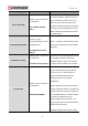
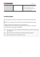


Table Of Contents
- AR-R5800 System
- 1.1 Specifications
- 1.2 Packing List
- 1.3 System Dissection
- 2.1 2.5” HDD Installation
- 2.2 CF Card Installation
- 2.3 Power Cord Hook Installation
- 2.4 PCIe Card Installation
- 2.5 Rack Bracket Installation
- 1.1 Specifications
- 1.2 Package Contents
- 1.3 Block Diagram
- 2.1 Locations (Top side)
- 2.2 Connectors and Jumper Setting
- 2.3 Connector and Jumper Setting
- Date Setup
- Time Setup
- IDE Channel 0 Master
- SATA Channel 1/2
- Halt On
- Quick Power On Self Test
- Full Screen Logo Show
- APIC Mode
- Pre-allocated Memory Size
- DVMT Mode
- Console Redirection
- Baud Rate
- LAN Bypass Function
- Reset Configuration Data
- Resources Controlled By
- IRQ Resources
- Onboard Serial Port 1
- Onboard Serial Port 2
- USB Device Setting
- USB 1.0 Controller
- USB 2.0 Controller
- USB Operation Mode
- USB Keyboard Function
- USB Storage Function
- First / Second / Third Boot Device/Other Boot Device
- LAN Boot Select
- Hard Disk Boot Priority
- Save & Exit Setup
- Load Optimized Defaults
- Exit Without Saving
- Set Password

Revision: 1.0
4
Software Installation and
Programming Guide
4.1 Introduction
LCD Control Module
Overview
The LCM (short for LCD Control Module) APIs provide interfaces to control the module. By
invoking these APIs, programmers can implement the applications which have the functions listed
below:
1. Clear LCD screen.
2. Turn on or off the cursor on the screen.
3. Move the cursor on the screen.
4. Turn on or off the text on the screen.
5. Get the identification of the pressed key of the LCM.
6. Show the text on the screen.
GPIO and Watchdog
Overview
AR-B5800 provides both a GPIO interface and a Watchdog timer. Users can use the GPIO and
Watchdog APIs to configure and to access the GPIO interface and the Watchdog timer. The GPIO
has eight ports. Users can configure each pin as input or output respectively. The Watchdog timer
can be set to 1~255 seconds. Setting the timer to zero disables the timer. The remaining seconds of
the timer to reboot can be read from the timer.
In this GPIO and Watchdog package, we provides:
1. API source code.
2. GPIO and Watchdog test utility and the utility source code.
Here is the GPIO Mapping Table:
49