
Manual


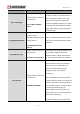
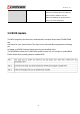
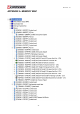

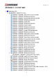

Table Of Contents
- AR-R5800 System
- 1.1 Specifications
- 1.2 Packing List
- 1.3 System Dissection
- 2.1 2.5” HDD Installation
- 2.2 CF Card Installation
- 2.3 Power Cord Hook Installation
- 2.4 PCIe Card Installation
- 2.5 Rack Bracket Installation
- 1.1 Specifications
- 1.2 Package Contents
- 1.3 Block Diagram
- 2.1 Locations (Top side)
- 2.2 Connectors and Jumper Setting
- 2.3 Connector and Jumper Setting
- Date Setup
- Time Setup
- IDE Channel 0 Master
- SATA Channel 1/2
- Halt On
- Quick Power On Self Test
- Full Screen Logo Show
- APIC Mode
- Pre-allocated Memory Size
- DVMT Mode
- Console Redirection
- Baud Rate
- LAN Bypass Function
- Reset Configuration Data
- Resources Controlled By
- IRQ Resources
- Onboard Serial Port 1
- Onboard Serial Port 2
- USB Device Setting
- USB 1.0 Controller
- USB 2.0 Controller
- USB Operation Mode
- USB Keyboard Function
- USB Storage Function
- First / Second / Third Boot Device/Other Boot Device
- LAN Boot Select
- Hard Disk Boot Priority
- Save & Exit Setup
- Load Optimized Defaults
- Exit Without Saving
- Set Password
Revision: 1.0
when you are prompted to enter the
password. A message will confirm that the
password will be disabled. Once the
password is disabled, the system will boot
and you can enter Setup freely.
3.8 BIOS Update
The BIOS program instructions are contained within computer chips called FLASH ROMs
that
are located on your system board. The chips can be electronically reprogrammed, allowing
you
to update your BIOS firmware without removing and installing chips.
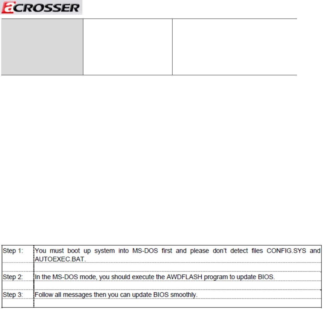
The AR-B5800 provides the FLASH BIOS update function for you to easily to update BIOS.
Please follow these operating steps to update BIOS:
44