
Manual
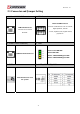
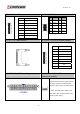

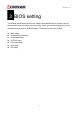


Table Of Contents
- AR-R5800 System
- 1.1 Specifications
- 1.2 Packing List
- 1.3 System Dissection
- 2.1 2.5” HDD Installation
- 2.2 CF Card Installation
- 2.3 Power Cord Hook Installation
- 2.4 PCIe Card Installation
- 2.5 Rack Bracket Installation
- 1.1 Specifications
- 1.2 Package Contents
- 1.3 Block Diagram
- 2.1 Locations (Top side)
- 2.2 Connectors and Jumper Setting
- 2.3 Connector and Jumper Setting
- Date Setup
- Time Setup
- IDE Channel 0 Master
- SATA Channel 1/2
- Halt On
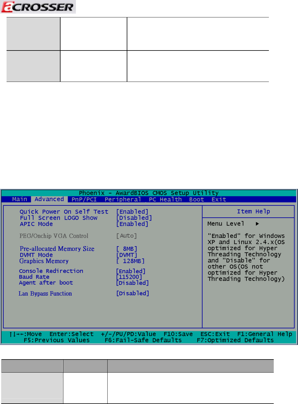
- Quick Power On Self Test
- Full Screen Logo Show
- APIC Mode
- Pre-allocated Memory Size
- DVMT Mode
- Console Redirection
- Baud Rate
- LAN Bypass Function
- Reset Configuration Data
- Resources Controlled By
- IRQ Resources
- Onboard Serial Port 1
- Onboard Serial Port 2
- USB Device Setting
- USB 1.0 Controller
- USB 2.0 Controller
- USB Operation Mode
- USB Keyboard Function
- USB Storage Function
- First / Second / Third Boot Device/Other Boot Device
- LAN Boot Select
- Hard Disk Boot Priority
- Save & Exit Setup
- Load Optimized Defaults
- Exit Without Saving
- Set Password
Revision: 1.0
SATA Channel
1/2
N/A
The onboard SATA connectors provide 1
channel for connecting one SATA hard disks,
the BIOS will auto-detect the SATA type.
Halt On
All Errors,
No Errors,
All but keyboard.
Select the situation in which you want the
BIOS to stop the POST process and notify
you.
3.2 Advanced Chipset Setup
This section allows you to configure and improve your system and follows you to set up
some system features according to your preference.
Option Choice Description
Quick Power On Self
Test
Enabled
Disabled
This category speeds up Power On Self Test (POST) after you
have powered up the computer. If it is set to Enable, BIOS will
shorten or skip some check items during POST.
37