
Manual
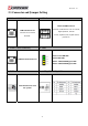
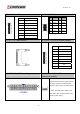


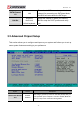
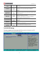
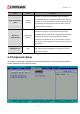

Table Of Contents
- AR-R5800 System
- 1.1 Specifications
- 1.2 Packing List
- 1.3 System Dissection
- 2.1 2.5” HDD Installation
- 2.2 CF Card Installation
- 2.3 Power Cord Hook Installation
- 2.4 PCIe Card Installation
- 2.5 Rack Bracket Installation
- 1.1 Specifications
- 1.2 Package Contents
- 1.3 Block Diagram
- 2.1 Locations (Top side)
- 2.2 Connectors and Jumper Setting
- 2.3 Connector and Jumper Setting
- Date Setup
- Time Setup
- IDE Channel 0 Master
- SATA Channel 1/2
- Halt On
- Quick Power On Self Test
- Full Screen Logo Show
- APIC Mode
- Pre-allocated Memory Size
- DVMT Mode
- Console Redirection
- Baud Rate
- LAN Bypass Function
- Reset Configuration Data
- Resources Controlled By
- IRQ Resources
- Onboard Serial Port 1
- Onboard Serial Port 2
- USB Device Setting
- USB 1.0 Controller
- USB 2.0 Controller
- USB Operation Mode
- USB Keyboard Function
- USB Storage Function
- First / Second / Third Boot Device/Other Boot Device
- LAN Boot Select
- Hard Disk Boot Priority
- Save & Exit Setup
- Load Optimized Defaults
- Exit Without Saving
- Set Password
Revision: 1.0
28. JP1 (For LAN1/LAN2 Bypass Function
Select.).
29. RTC1
Pins 1 and 2 shorted
(Default): Forced Normal.
Pins 2 and 3 shorted:
Controlled By CPLD.
Otherwise : Forced Bypass
CMOS Backup Battery:
An onboard battery saves the CMOS memory to
keep the BIOS information stays on even after
disconnected your system with power source.
Nevertheless, this backup battery exhausts after
some five years.
Once the error message like “CMOS BATTERY
HAS FAILED” or “CMOS checksum error”
displays on monitor, this backup battery is no
longer functional and has to be renewed
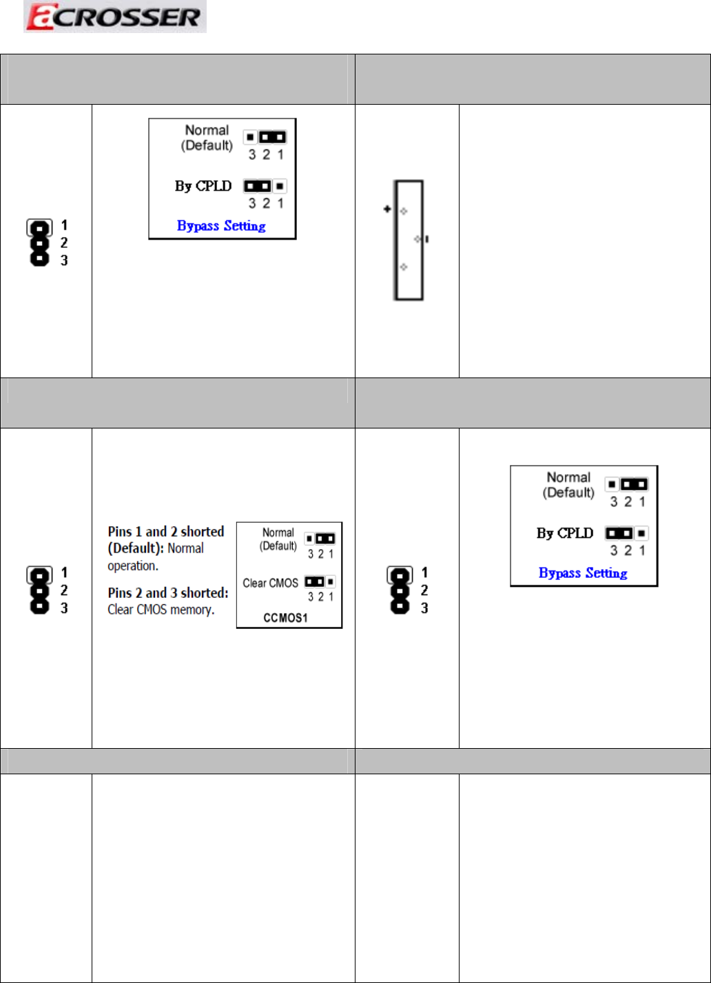
30. CCMOS1. 31. JP4 (For LAN3/LAN4 Bypass Function
Select.).
Pins 1 and 2 shorted
(Default): Forced Normal.
Pins 2 and 3 shorted:
Controlled By CPLD.
Otherwise : Forced Bypass
34