
Manual
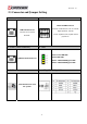
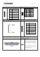
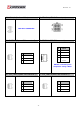


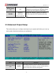
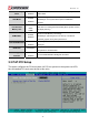
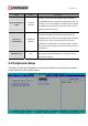

Table Of Contents
- AR-R5800 System
- 1.1 Specifications
- 1.2 Packing List
- 1.3 System Dissection
- 2.1 2.5” HDD Installation
- 2.2 CF Card Installation
- 2.3 Power Cord Hook Installation
- 2.4 PCIe Card Installation
- 2.5 Rack Bracket Installation
- 1.1 Specifications
- 1.2 Package Contents
- 1.3 Block Diagram
- 2.1 Locations (Top side)
- 2.2 Connectors and Jumper Setting
- 2.3 Connector and Jumper Setting
- Date Setup
- Time Setup
- IDE Channel 0 Master
- SATA Channel 1/2
- Halt On
- Quick Power On Self Test
- Full Screen Logo Show
- APIC Mode
- Pre-allocated Memory Size
- DVMT Mode
- Console Redirection
- Baud Rate
- LAN Bypass Function
- Reset Configuration Data
- Resources Controlled By
- IRQ Resources
- Onboard Serial Port 1
- Onboard Serial Port 2
- USB Device Setting
- USB 1.0 Controller
- USB 2.0 Controller
- USB Operation Mode
- USB Keyboard Function
- USB Storage Function
- First / Second / Third Boot Device/Other Boot Device
- LAN Boot Select
- Hard Disk Boot Priority
- Save & Exit Setup
- Load Optimized Defaults
- Exit Without Saving
- Set Password
Revision: 1.0
15. LCM1 ( for LCM use ) 16. GP1 ( GPIO Header )
Pin SIGNAL
1 Pull-High to VCC5
2 VCC5
3 SOUTB
4 SINB
5 RTSB#
6 CTSB#
7 GND
AL PIN SIGNAL PIN SIGN
1
VCC_G
D P
2
GN
3
34 GP30
4
GP
5
35 GP31
6
GP
7
36 GP32
8
GP
9
7
GP33
10
GP3
17. CF1 ( CF CARD Socket ) 18. CPLD1 ( for CPLD Firmware Update)
Pin SIGNAL
1 3VDUAL
2 G_TDO
3 G_TDI
4 NC
5 NC
6 G_TMS
7 GND
8 G_TCK
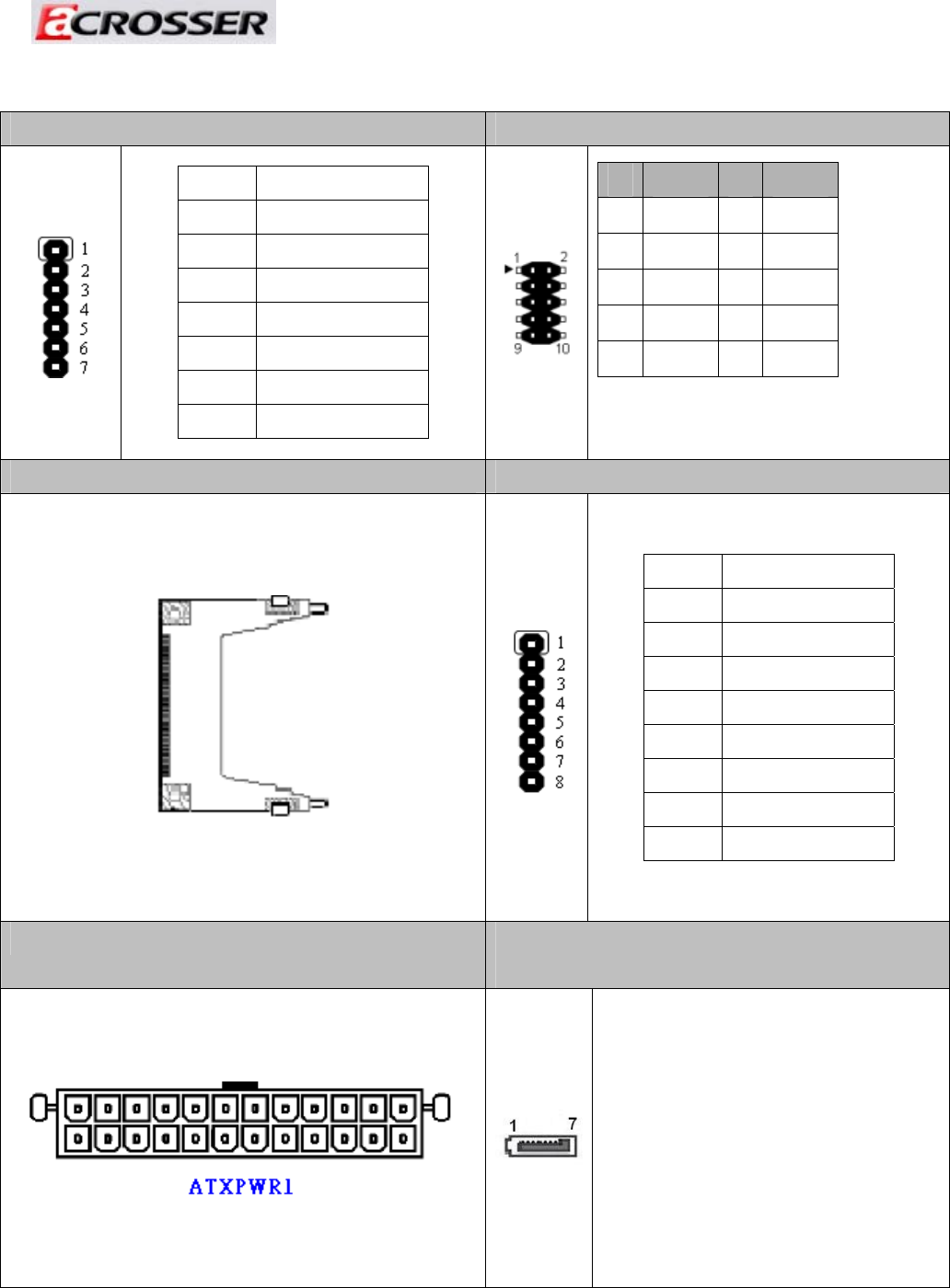
19. ATXPWR1 ( ATX Power Supply Input ) 20,21. SATA1, SATA2 (SATA device
connector #1 and #2).
To connect SATA device:
1.Attach either end of the signal cable to
the SATA connector on motherboard.
Attach the other end to the SATA device.
2. Attach the SATA power cable to the
SATA device and connect the other end
from the power supply.
32