
Manual
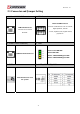
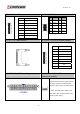


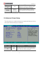
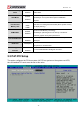
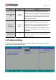

Table Of Contents
- AR-R5800 System
- 1.1 Specifications
- 1.2 Packing List
- 1.3 System Dissection
- 2.1 2.5” HDD Installation
- 2.2 CF Card Installation
- 2.3 Power Cord Hook Installation
- 2.4 PCIe Card Installation
- 2.5 Rack Bracket Installation
- 1.1 Specifications
- 1.2 Package Contents
- 1.3 Block Diagram
- 2.1 Locations (Top side)
- 2.2 Connectors and Jumper Setting
- 2.3 Connector and Jumper Setting
- Date Setup
- Time Setup
- IDE Channel 0 Master
- SATA Channel 1/2
- Halt On
- Quick Power On Self Test
- Full Screen Logo Show
- APIC Mode
- Pre-allocated Memory Size
- DVMT Mode
- Console Redirection
- Baud Rate
- LAN Bypass Function
- Reset Configuration Data
- Resources Controlled By
- IRQ Resources
- Onboard Serial Port 1
- Onboard Serial Port 2
- USB Device Setting
- USB 1.0 Controller
- USB 2.0 Controller
- USB Operation Mode
- USB Keyboard Function
- USB Storage Function
- First / Second / Third Boot Device/Other Boot Device
- LAN Boot Select
- Hard Disk Boot Priority
- Save & Exit Setup
- Load Optimized Defaults
- Exit Without Saving
- Set Password
Revision: 1.0
2.3 Connector and Jumper Setting
1. LAN1 ~ LAN8 RJ45 Connector 9. USB1 Connector
LAN RJ45 Connector
Connects to Local Area
Network.
External USB Connector
Connects to USB devices such as scanner,
digital speakers, monitor
, mouse, keyboard, hub, digital camera,
joystick etc.
10. COM1 ( RJ45 Connector ) 11. LED1
COM Port RJ45 Connector
Green1: Power ON LED.
Green2: HDD LED
Yellow1: LAN3&LAN4 Bypass LED.
Yellow2: LAN1&LAN2 Bypass LED.
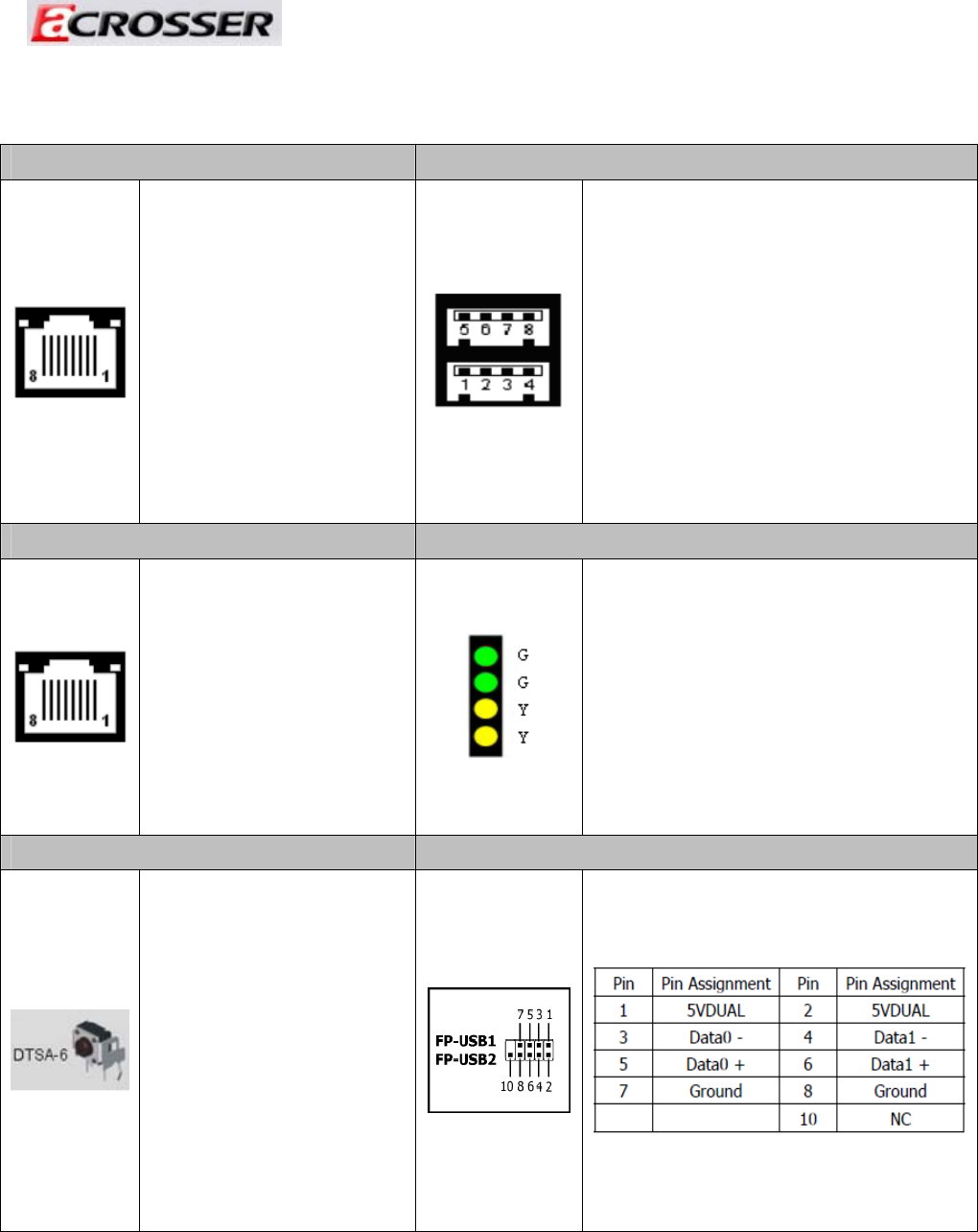
19. RST2 13,14. FP_USB1 & FP_USB2
Push this button to reset
the system.
31