AMB-IH61T3 Board User Manual 1
Copyright All Rights Reserved. Manual’s first edition: For the purpose of improving reliability, design and function, the information in this document is subject to change without prior notice and does not represent a commitment on the part of the manufacturer. The manufacturer shall not be liable for direct, indirect, special, incidental, or consequential damages arising out of the use or inability to use the product or documentation, even if advised of the possibility of such damages.
Table of Contents Chapter 1 Introduction ............................................................. 4 1.1. Specifications............................................................................................. 4 1.2. Package Contents ...................................................................................... 6 Chapter 2 H/W Information ...................................................... 7 2.1. 2.2. Mainboard illustration ...............................................................
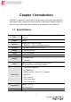
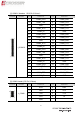
Chapter 1 Introduction AMB-IH61T3 with Intel Pentium/Core i3/i5/i7 processor is a multi-function Industrial main-board, which is suitable for using in all kind of applications. Besides it basic I/O ports like VGA, USB, COM. LAN, and GPIO, it can expand to 10 x COM ports. 1.1.
Dimension 170 x 170mm Notes: [1]: Due to the restriction of Windows 32 bit OS, when applied more than 4G memory, 32 bit OS may detect less than actual size. [2]: COM3 can be RS232 or RS485 by setting jumpers. [3]: It is recommended to use CPUs those TDP no higher than 77W.
1.2. Package Contents Check if the following items are included in the package.
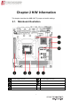
Chapter 2 H/W Information This chapter describes the AMB-IH61T3 jumper and switch settings. 2.1.
LPT Connector PS/2 Connector COM Connector VGA1 Connector LAN Connectors USB Connectors Audio Connector VGA2 Connector Note. It can not use USB Hub with power adaptor that connects to USB port.
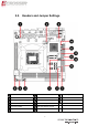
2.2.
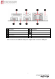
[1] COM3-6 Headers(20*2 Pin 2.
[3] COM3 Signal selection Jumpers (3*1 Pin 2.0mm) Location Jumper Setting Function JP1 JP2 1-2 RS232 2-3 RS485 [4] System Fan Connector (3*1 Pin 2.54 mm) Location Connector SYS_FAN Pin Definition Pin Definition 1 GND 2 +12V 3 FAN TAC [5] Front Panel Header(5*2 Pin 2.
[7] Audio Header(5*2 Pin 2.54 mm) Location Header F_AUDIO1 Pin Definition Pin Definition 1 FRONT_MIC_L 2 GND 3 FRONT_MIC_R 4 + 3.3 V 5 FRONT_OUT_R 6 GND 7 RRONT_Jack Detect 9 FRONT_OUT_L 10 GND [8] CPU Fan Connector (4*1 Pin 2.54 mm) Location Connector CPU_FAN Pin Definition Pin Definition 1 GND 2 +12V 3 FAN TAC 4 FAN PWM [9] Front USB Headers (5*2 Pin 2.
[11] LVDS VDD selection Jumper(3*2 Pin 2.54 mm) Locatio n Jumper LVDS_P1 Setting Function 1-3 VDD=12V 3-5 VDD=3.3V 2-4 or 4-6 VDD=5V [12] LVDS Signal Header(15*2 Pin 2.
[14] RS485 Header (COM3, 3*1 Pin 2.54mm) Location Header J_1 Pin Definition Pin Definition 1 RS485- 2 GND 3 RS485+ [15] COM7-10Headers(20*2 Pin 2.
Chapter 3 BIOS Settings This chapter describes the BIOS menu displays and explains how to perform common tasks needed to get the system up and running. It also gives detailed explanation of the elements found in each of the BIOS menus.
3.1. Main Setup Once you enter the AMI Setup Utility, the Main menu will appear on the screen. Use the arrow keys to highlight the item and then use the < + > < - > keys to select the value you want in each item. Note: Listed at the bottom of the menu are the control keys. If you need any help with the item fields, you can press the key, and it will display the relevant information.
System Date N/A Set the date. Use Tab to switch between Date elements. System Time N/A Set the time. Use Tab to switch between Time elements. Access Level N/A This item displays the level of users.
3.2. Advanced Setup Option Choice ACPI Settings N/A This item display system ACPI parameters. Power On N/A This item display system power on settings after power fail. LVDS Configuration N/A This item display LVDS panel parameters. CPU Configuration N/A This item displays the CPU configuration parameters. SATA Configuration N/A This item displays the SATA devices configuration. Super I/O N/A This item displays the system super I/O chip configuration.
3.2.1. ACPI Settings Setup Option Choice ACPI Auto Disabled, Configuration Enabled Enable Hibernation ACPI Sleep State Disabled, Enabled Disabled, S1only Description Enables or disables BIOS ACPI Configuration. Enables or disables Hibernation mode. Set ACPI sleep state is disabled or S1 mode only.
3.2.2. Power On Setup Option Choice PowerOn after Power On, Power PowerFail Off, Last Status Description This item defines the AC power state when power is re-applied after a power failure.
3.2.3.
3.2.4. CPU Configuration Setup It display the CPU configuration information.
3.2.5. SATA Configuration Setup Option Choice SATA Controller Enabled, Disabled SATA Mode Selection Serial ATA Port 1/2 Description Enable or disable support for SATA device. IDE This item defines the configuration of SATA controller N/A This item displays the SATA port 1/2 device.
3.2.6. Super I/O Setup Option Choice Description Super I/O Chip N/A This item displays the Super I/O model name. COM1 ~ COM6 N/A This item displays the COM1 ~ COM6 parameters. LPT N/A This item displays the LPT parameters.
3.2.6.1. COM1 ~ COM6 Setup Option Choice Serial Port Enabled, Disabled Device Setting N/A Change Settings Description Enable or disable support for COM1~COM6 This item displays the IO address and IRQ of COM1~COM6 Auto, other settings This item selects IO port and IRQ parameters.
3.2.6.2. LPT Setup Option Choice Parallel Port Enabled, Disabled Device Settings N/A Change Settings Auto, other settings Description Enabled or disabled the support of LPT port This item displays the IO address and IRQ of LPT port This item select IO port and IRQ parameters. STD Printer Mode, SPP Mode, EPP-1.9 and SPP Mode, Device Mode EPP-1.7 and SPP Mode, ECP Change the LPT port mode. Mode, ECP and EPP 1.9 Mode, ECP and EPP 1.
3.2.7. Hardware Monitor Setup Remark: After you clear CMOS info, please load optimized default CMOS setting and reboot your system.
3.2.8. COM7/8/9/10 Configuration Setup Option Choice Description Super I/O Chip N/A This item displays the Super I/O model name. COM7 ~ COM10 N/A This item displays the COM7 ~ COM10 parameters.
3.2.8.1. COM7~COM10 Setup Option Choice Serial Port Enabled, Disabled Device Setting N/A Change Settings Description Enable or disable support for COM7~COM10 This item displays the IO address and IRQ of COM7~COM10 Auto, other settings This item selects IO port and IRQ parameters.
3.3. Chipset Setup Option Choice PCH-IO Configuration N/A This item displays the PCH parameters. N/A This item displays the System Agent parameters.
3.3.
3.3.1.1. PCI Express Configuration Setup Option Choice Description PCI Express Port 1 N/A This item displays the PCI Express Port 1 parameter. PCI Express Port 2 N/A This item displays the PCI Express Port 2 parameter. PCI Express Port 3 N/A This item displays the PCI Express Port 3 parameter.
Option Choice PCI Express Port 1 Enabled, Disabled Description Enabled or disabled the PCI Express Port 1 Set the ASPM Level: ASPM Support Disabled, Force L0, Force L0s - Force all links to L0s State Auto AUTO - BIOS auto configure DISABLED - Disable ASPM 33
3.3.1.2.
3.3.1.3. PCH Azalia Configuration Setup Option Azalia Choice Enabled, Disabled, Auto Description Enabled or disabled the Azalia controller.
3.3.2. System Agent Configuration Setup Option Graphics Configuration Memory Configuration Choice Description N/A This item displays the graphics parameter. N/A This item displays the memory parameter.
3.3.2.1. Graphics Configuration Setup Option Choice Description Select which of IGFX/PEG/PCI Graphics Primary Display Auto / IGFX / PEG device should be Primary Display 0r select SG for Switchable Gfx. GTT Size 1MB / 2MB Select the GTT Size Aperture Size 128MB / 256MB / 512MB Select the Aperture Size 32M / 64M / 96M / 128M / 160M / 192M / 224M / 256M / Select DVMT 5.
3.3.2.2.
3.4. Boot Setup Option Bootup NumLock State Choice On, Off Full Screen Logo Enabled, Disabled Fast Boot Disabled / Enabled Description Select the Keyboard NumLock state. Enabled or disabled the fullscreen logo support. Enables or disables boot with initialization of a minimal set of devices required to launch active boot option.
3.5. Security Setup Option Administrator Choice Description N/A Set the administrator password User Password N/A Set the user password Secure Boot Enabled, Disabled Secure Boot Mode Standard, Custom Password Secure Boot flow control. Secure Boot is possible only if System runs in User Mode. Default is enabled. Select Secure Boot mode.
3.6. Save & Exit Setup option Choice Description Save Changes and Pressing on this item for Exit save changes and exit. Discard Changes and Pressing on this item for Exit Save Changes and Reset discard changes and exit. Exit system setup after saving the changes. Exit system setup without saving any changes. Pressing on this item for confirmation : save configuration and reset 41 Reset the system after saving the changes.
Discard Changes and Reset Pressing on this item for confirmation: reset without save changes Pressing on this item for Save Changes confirmation: save previous change values Pressing on this item for Discard Changes confirmation: without save previous Save Changes done so far to any of the setup options. Discard Changes done so far to any of the setup options. change values Pressing on this item for Restore Defaults Reset system setup without saving any changes.
FAQ Does my system support Fedora and Linux basic? The system has been verified with Fedora 17 and Linux basic. monitor into VGA2 connector.
Acrosser service contact info: We deeply appreciate you purchase Acrosser products. If you have any questions or problems about Acrosser products, the following is the suggested procedures: We will answer your questions a.s.a.p. 1) Describe your info and Acrosser system info A. Your company name: _____________ B. Your contact info: ____________________ & phone number: _________________ C. Your e-mail address: ______________________ D.
Acrosser Headquarters 新北市三重區重新路五段609巷12號10樓 10F., No.12, Lane 609, Sec. 5, Chongsin Rd., Sanchong District, New Taipei City 241, Taiwan, R.O.C. TEL: +886-(0)2-2 9999 000 FAX: +886-(0)2-2999-2887 Acrosser Taichung Office 台中市南屯區河南路四段162號12樓之6 12-6, No.162, Sec. 4, Henan Rd., Nantun Dist., Taichung City 408, Taiwan R.O.C. TEL: +886-(0)4-2251-0659 FAX: +886-(0)4-2254-6079 Acrosser China Subsidiary 欣扬通电子有限公司 深圳分公司 深圳市福田区车公庙泰然九路21号 皇冠科技园3栋2楼东面A区 (邮编:518040) A East 2F 3th Building, Crown Estate No.