
User Guide


Y1-03-0180 Rev. A
6
SECTION 3 - INSTALLATION
3.1 Preparation
3.1.1 Parts included:
Beacon/Mounting Bracket Assy Qty: 1 PN: A3-06-2410-1
Cross Dipole Antenna Qty: 1 PN: 2810
SMA Male Conn, RG-8/U Crimp Qty: 1 PN: 2814
Activation Switches Qty: 2 PN: 2820
Antenna Mount Qty: 1 PN: 2821
TNC Male Conn, RG-8/U Crimp Qty: 1 PN: 2633
Insulated Terminals, Crimp Qty: 4 PN: A1-05-0125-17
3.1.2 Tools Needed:
Phillips screwdriver
Drill
RG-8/U Crimp tool
Saw
Solder Iron
3.1.3 Additional Materials Needed for Installation:
Marine Grade RG-8/U Coaxial Cable
Switch wire or cable
Screws/Bolts for mounting bracket (3/16” or #10)
Screws/Bolts for Antenna Mount
3.2 Beacon Installation
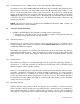
3.2.1 The ThunderBird SSAS is shipped attached to its mounting bracket. Typically, the beacon must
be removed from the mounting bracket during installation. The beacon can be removed from the
mounting bracket as follows:
• First disconnect the 2-Pin waterproof connector on the left side of the beacon.
• Unbuckle the strap holding the beacon to the bracket.
The ThunderBird SSAS is intended to transmit covertly a security alert, notifying competent
authorities that the security of the vessel is under threat or has been compromised. A key
component of the system is its covert nature, which should be maintained as much as possible to
protect the beacon from malicious tampering.
The ThunderBird SSAS is shipped in the “OFF” position. During the installation procedure,
leave the beacon in the “OFF” position to prevent false alarms.
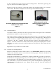
3.2.2 Mounting location
The location selected must be sufficiently rigid to support the weight of the total installation
(approx. 2 lbs) and at the same time consider vibration, exposure to surrounding hazards, such as
equipment movement, doors openings, personnel traffic, etc. The bracket should only be
mounted to a flat surface at least as big as the bracket. Mounting to a rail or post is not
recommended.