
User Guide


Y1-03-0180 Rev. A
12
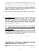
Connect the male TNC cable assembly to the mating female TNC connector on antenna.
Route cable to SSAS beacon as needed, making sure to adequately secure the cable. Provide a
drip loop in the cable near the beacon to prevent water from running directly on to the beacon.
Trim the cable to the appropriate length.
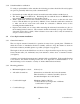
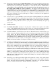
Attach male SMA connector (supplied) to marine grade RG-8/U coaxial cable as follows:
• Strip the coax cable per Figure 8.
• Solder the connector pin to the center conductor.
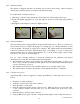
• Slide the ferrule over the cable.
• Slide the cable/pin assembly into the connector body. Make sure the pin goes into the center
of the connector insulator and the braid goes over the knurled part of the back of the
connector.
• Slide the ferrule to the back of the connector.
• Using an RG-8/U die (approx. 0.429”), crimp the ferrule tightly over the cable and connector.
Connect the male SMA connector on the cable assembly to the mating female SMA connector on
the beacon.
3.4.6 Antenna Installation Verification
To verify proper installation of the Cross Dipole antenna, the following procedure should be
followed (requires two persons, preferably with 2-way radio communications):
• One person should be on the deck with an FPR-100 with line-of-sight view of the Cross
Dipole antenna. The FPR-100 antenna should be oriented horizontally and ideally be located
directly under the Cross Dipole antenna.
• With the FPR-100 ready to receive a test burst, the other person should initiate a Self-Test.
• If the FPR-100 successfully receives the test burst, then the Cross Dipole antenna is installed
correctly.
• The FPR-100 can also verify that the ThunderBird SSAS is programmed correctly.
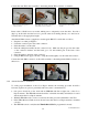
Slide wire thru mounting bracket to
connect to antenna
Fasten TNC cable assembly to the mating
female TNC connector on antenna
Secure antenna to the mounting
bracket