
User Guide


Y1-03-0180 Rev. A
11
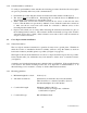
3.4.3 Antenna assembly
The antenna is shipped with the four elements removed from the housing. Before using the
antenna, these elements must be assembled to the antenna housing.
For each element, assemble as follows:
1. Slide the grooved end of the element into a hole in the side of the housing until it stops
2. Install and tighten appropriate set screw through hole in the bottom housing using included
wrench
3. Pull lightly on the element to ensure it is tightly secured
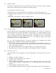
3.4.4 Antenna installation
Select mounting location using guidelines and general information above. The top of a mast is an
ideal location for the cross dipole. Mounting to an existing spar or to a bracket attached to a mast
is also acceptable. See Figure 6 on page 22 for examples. The antenna must be mounted with the
connector pointing down and the elements horizontal. If mounting on a spar or bracket, the
antenna elements must be oriented approximately 45° to the horizontal support when looking
from the top or bottom, as shown in Figure 6.
Use one of the following methods to mount the antenna per the guidelines and general
information above with all four elements in the horizontal plane:
• The included mount can be used to attach to any small, flat, horizontal surface; i.e. the top of a
mast or a spar. In this case drill holes in the pattern of the mount and attach with marine grade
screws as needed (not supplied).
• The included mount can be used to attach the antenna to a round spar using U-bolts.
• The antenna can be mounted to any bracket or mast with the standard 1” x 14 thread.
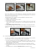
3.4.5 Connection to beacon
Attach male TNC connector (supplied) to marine grade RG-8/U coaxial cable (Not provided) as
follows:
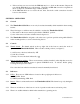
• Strip the coax cable per Figure 7.
• Solder the connector pin to the center conductor.
• Slide the ferrule over the cable.
• Slide the cable/pin assembly into the connector body. Make sure the pin goes into the center
of the connector insulator and the braid goes over the knurled part of the back of the
connector.
• Slide the ferrule to the back of the connector.
• Using an RG-8/U die (approx. 0.429”), crimp the ferrule tightly over the cable and connector.
1.
2.
3.