
User Guide


Y1-03-0180 Rev. A
10
3.3.6 Switch installation verification
To verify proper installation of the switches, the following procedure should be followed (requires
two persons, preferably with 2-way radio communications):
• Perform this procedure with all connections made between the switches and the beacon.
• The beacon must be in OFF mode. Performing this test with the beacon in READY mode
may result in a live transmission to the satellite system.
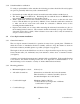
• With a multi-meter, measure the resistance between the two screws on the left side of the
beacon. This should be an open circuit (> 100 kΩ.) If not, check the switch wire connections
to make sure the two wires from each switch are connected to different screws on the
mounting bracket terminal block.
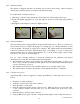
• Depress each switch (one at a time) while measuring the resistance between the two pins on
the mounting bracket connector. The resistance should momentarily (as long as the switch is
depressed) read a short (< 10Ω.) If the resistance never reads a short, verify all connections
are per 3.2.4 and 3.2.5 above.
3.4 Cross dipole antenna installation
3.4.1 General information
The cross dipole antenna is intended for operation far away from a ground plane. With this in
mind, the location of installation should be carefully selected to keep the antenna as far from
horizontal conductive (metallic) planes as possible (see figure 6 on page 22).
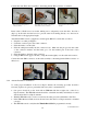
The length of cable from the SSAS beacon to the cross dipole should be kept as short as possible.
Secure antenna cable (3 ft. maximum) away from antenna to reduce stress on antenna connector
(see figure 9).
A stainless steel 4 inch tall antenna mount is included with your SSAS kit. If the supplied bracket
is not ideal for the desired mounting location, the cross dipole has a standard female 1” x 14
thread allowing it to be mounted to a variety of off-the-shelf brackets and masts.
3.4.2 Mounting guidelines
• Minimum height above deck: 10 feet (3 m)
• Allowable obstructions: Obstructions are allowable only below the antenna.
There should be no conductive (metallic) objects in
the entire hemisphere above the antenna.
• Coaxial cable length: Maximum: 100 feet (30.5 m)
* Contact the factory if longer runs or different
coaxial cable is required.
• Coaxial cable type: RG-8/U Marine Grade