
User Guide


Y1-03-0180 Rev. A
9
for 16 to 22 AWG wire for the connection to the mounting bracket. Other marine grade lugs (Not
Supplied) can be used for different gauge wire.
Because two wires are required to connect the switch to the mounting bracket, a two conductor
cable is ideal. This makes routing the wire easier and provides additional strength.
3.3.4 Switch installation
Cut a 0.638” x 0.638” (16.2 mm x 16.2 mm) square hole in the selected panel. The recommended
panel thickness is 0.039” to 0.106” (1.0 mm to 3.2 mm).
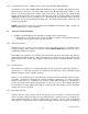
The switch should be pushed back into the hole from the front. It is recommended to make the
wire connections before installing the switch into the panel. Connect the wires to the back of the
switch; one wire to “COM” terminal and the other to “N.O.” terminal. There should be no
connection to the “N.C.” terminal. The wires should be soldered to the switch terminals (see
figure 2). Once the connections are made, make sure the spring-loaded switch guard is securely
attached to the switch and press the switch assembly into the panel hole. The switch will snap
into place.
Repeat the above procedure for the other switch.
3.3.5 Connection to mounting bracket
Route the switch wire from the switch locations to the ThunderBird SSAS beacon mounting
bracket. Care should be taken to route and secure the wire properly. The wires should then be
trimmed to the appropriate length.
If using the recommended 16 to 22 AWG wire, crimp the terminal lugs (provided) onto the wires.
If other wire is used, appropriate lugs (Not provided) can be used. Alternatively, the wire can be
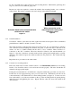
connected directly to the terminal block on the mounting bracket (see figure 3). Connect one wire
from each switch to one of the two terminals on the top of the mounting bracket by placing the lug
under the screw and tightening the screw. Repeat with the other wire from each switch in the
other terminal.
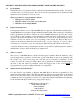
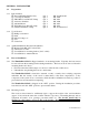
Activation button with recommended wire
soldered to the switch
Figure
2
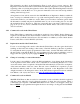
Wiring connection on the
mounting bracket coming from
Activation switch
Figure 3