
Specifications


SmartReader Plus Data Loggers
103
Copyright © 2010 ACR Systems Inc. All Rights Reserved.
1.20.4 Shielded Network
The Shielded Network accommodates a maximum of ten loggers.
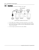
Figure G-3: Shielded SmartReader Plus Network
1. Insert Y-adaptor cables (YA-200) into each logger on the network.
2. Connect the IC-101 Interface Cable to the first logger.
3. Connect all the loggers to each other, using shielded cable.
4. Connect the Network Power Supply (PS-201) to the last logger using the available end of
the Y-adaptor cable.
5. Plug the power supply into an electrical outlet.
1.20.5 Connection Problems and Solutions
Network communication can be affected by:
· network cable length
· type of network cable
· number of loggers on network
· interference from electrical equipment
· lack of external power supply
If you have problems communicating with loggers on a network please try the following steps: