
Specifications


SmartReader Plus Data Logger
102
Copyright © 2010 ACR Systems Inc. All Rights Reserved.
1.20.3 Modular Network
The Modular Network accommodates a maximum of ten loggers.
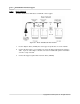
Figure G-2: Modular SmartReader Plus Network
1. Insert a Y-adaptor cable (YA-200) into the last logger on the network.
2. Insert a Modular Y-adaptor (YA-201) into:
· the plug portion of the IC-101 Interface Cable
· each logger except the last one on the network
· one end of the last logger's Y-adaptor cable
3. Cut and crimp the Modular Flat Cable.
NOTE: Do not use modular cable crimped for telephone use as the wiring will be
"mirror image". Instead, crimp your own jacks using a "straight through" wiring
method.
4. Connect the IC-101 to the first logger, and all the loggers to each other, using Modular
Flat Cable.
5. Connect the Network Power Supply (PS-201) to the last logger using the available end of
the Y-adaptor cable.
6. Plug the power supply into an electrical outlet.