In the United States WARNING: It is a violation of the rules of the Federal Communications Commission to input an MMSI that has not been properly assigned to the end user, or to otherwise input any inaccurate data in this device. WARNING: This product is a supplemental navigation tool only! The user assumes all responsibility associated with the use of this device and safe navigation.
Table of Contents SECTION 1 - WHAT IS AIS? ____________________________________________________________ 4 SECTION 2 - INSTALLATION ___________________________________________________________ 6 SECTION 3 - USING THE TRANSPONDER ________________________________________________ 20 SECTION 4 - MAINTENANCE _________________________________________________________ 22 APPENDIX A - SERIAL DATA INTERFACE _________________________________________________ 22 APPENDIX B - SPECIFICATIONS AND WARNINGS __________________
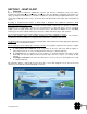
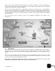
SECTION 1 - WHAT IS AIS? 1. Overview AIS is an acronym for Automatic Identification System. AIS increases navigational safety and collision avoidance by transmitting vessel identification, helping to reduce the difficulty of identifying ships when not in sight (e.g. at night, in radar blind arcs or shadows or at distance) by broadcasting navigational intentions to other vessels by providing ID, position, course, speed and other ship data with all other nearby ships and land based stations.
On the bottom, a typical Nauticast™-B AIS installation in a common environment is shown. The Nauticast™-B AIS is connected to the vessel‟s power supply, and, in connection with the VHF and GPS antennas, the minimal requirements for transponder operation are fulfilled. Both vessels in the above illustration are equipped with an AIS transceiver.
In order to meet carriage requirements for Class A and Class B AIS systems, dedicated GPS and VHF antennas must be fit to the transponders. ACR has included GPS and VHF antennas that have been specifically designed, tested and approved for use with the Nauticast™-B. ACR Electronics Inc. does not recommend or support using other antennas or sharing data information from existing shipboard installations. Class B AIS transponders will transmit data to other AIS equipped vessels and shore base stations.
2. Installation overview and prerequisites In the United States WARNING: It is a violation of the rules of the Federal Communications Commission to input an MMSI that has not been properly assigned to the end user, or to otherwise input any inaccurate data in this device.
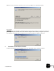
Or, when you have downloaded an upgrade: Unzip the package when necessary and start the installer program as described in “Installation of the Link2AIS™ Software” (later in this section). If one of the following dialogs is shown when the installation process is started, the .NET® framework and/or the Windows® Installer needs to be installed. See the following sections for the installation of these required products.
When you are not connected to the internet, an error message like the one below will be shown. From the CD If you do not want to download the .NET® framework from the Microsoft website, terminate the download process by clicking the “Cancel” button in the download dialog box and install the package directly from the CD. Locate the file “dotnetfx.exe” and double-click it to start the installation. Follow the instructions. 5.
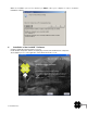
When the installation process has finished, you MUST reboot your computer in order to install the Link2AIS™ Software: 6. Installation of the Link2AIS™ Software Unzip the downloaded package when necessary. Locate the files “setup.exe” and the accompanying “msi” file, then double-click on “setup.exe” The installation process of the application starts with the Welcome screen: 10 Y1-03-0222 Rev.
A dialog box will appear reminding you to uninstall any prior versions of the Link2AIS™ software (if applicable) before continuing the install process. Read through and accept the license agreement and click Next. 11 Y1-03-0222 Rev.
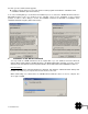
The next screen will allow you to pick options to be installed. These options are checked by default. Choose a directory where the software will be installed. Make note of this directory, as you will need to manually copy files to this location later on in the install process. 12 Y1-03-0222 Rev.
The software will ask you to choose a location in the Start menu to place the program‟s shortcuts: The next screen will ask you to confirm the install settings you have provided in the previous steps: 13 Y1-03-0222 Rev.
Now the application will install automatically in the folder you have chosen: The install program will tell you when installation has been completed. Click Finish. Finally, find the Coastlines folder on the installation CD and copy to the install directory chosen during the install process. If you are unable to find this directory, you can right-click the program icon on your desktop or in the Start menu, go to Properties, and look at the location shown in the “Start In” field. 14 Y1-03-0222 Rev.
You will find the installed program shortcuts in the Start Menu / All Programs/ ACR Electronics directory (unless you chose a different location during the install process). A shortcut named “Link2AIS” will be placed on your desktop. Use either shortcut to launch the program. 7. Connecting to a personal computer (PC) NOTE: To program your Nauticast™-B AIS you will need to connect the AIS to a personal computer and supply the Nauticast™-B AIS with 12V of power.
Start up Link2AIS™ Software program on PC. The initial application screen will appear as shown: The application requires a serial connection to a Nauticast™-B AIS transponder. Connect the transponder to an available serial port. If your serial port is not located in the drop down box, select „New…‟ and create a new connection. Select the serial port from the drop down menu, then click 'Connect': Once a connection is established, the application is ready to use.
To configure the transponder all of the data fields must be completed and saved to the AIS. WARNING: Per FCC rules (United States users only) the static data of the vessel cannot be changed once programmed. Do not program the static data unless you are certain you have the correct information. Please check the number entered carefully. If the static data programmed is incorrect the AIS transponder will need to be returned to ACR Electronics for factory reset.
Click the 'Yes' button if the MMSI is correct. The static data tab will be updated to show the newly programmed vessel information. The MMSI number will be displayed with a grey background to indicate that it has been programmed and cannot be changed. For additional software applications unrelated to the installation, please refer to the Link2AIS™ Software user guide for technical support. 11. Hardware installation WARNING: The compass safe distance of this unit is 0.5m or greater for 0.3° deviation.
If using PC serial terminal with third party AIS capable Electronic Charting Software, connect the user end of the data interface cable to the display device. The software in the display device must be configured for AIS operation AND to accept standard Class B AIS operation NMEA sentences. This external display unit software is not part of the Nauticast™-B AIS transponder package. By rule, Class B AIS devices must output serial data.
The GPS antenna has a free view through 360 degrees with a vertical angle of 5 to 90 degrees above the horizon. The GNSS antenna is placed as far away as possible from radar, Inmarsat and Iridium transmitters. Also ensure that the GPS antenna is free from direct view of the radar and the Inmarsat beam. The received GPS signal is very sensitive to noise and interference generated by other onboard transmitters.
If the red LED illuminates continuously, the unit should be assumed to be faulty. It should either be switched off (power removed) or, if this is not practical, any other vessel position information derived from the unit should not be used. It should also be assumed that the unit is not transmitting valid position information for your vessel. The unit should be examined by a competent equipment maintainer at the earliest opportunity. More details on LED indications can be found in “LED Indicators” (below).
TX timeout This is a yellow LED which indicates when lit that the CSTDMA transmitter is prevented from transmitting. Reasons for this include the following: The transponder‟s internal GPS receiver is not yet ready. The yellow LED will go out and the green LED will light when GPS receiver is ready. The transponder was unable to transmit an AIS message due to the channel being already occupied, e.g. by transmissions from other AIS transponders. Wait 10 minutes and verify GPS antenna connection.
Data A minimum keypad and display (MKD) unit, chart plotter or other display device may be connected to the Nauticast™-B AIS unit via the appropriate cable assembly. The default baud rate of the data link is 38.4k baud with 8 data bits, one stop bit and no parity. The data interface conforms to IEC 61162-1. VDM, VDO, ACA, ACS, ALR, TXT and ACK messages conform to NMEA 0183. Please refer to NMEA 0183 for full details of these AIS messages. 2.
NOTE 2 The sequential message identifier provides a message identification number from 0 to 9 that is sequentially assigned and is incremented for each new multi-sentence message. The count resets to 0 after 9 is used. For a message requiring multiple sentences, each sentence of the message contains the same sequential message identification number. It is used to identify the sentences containing portions of the same message.
5. VHF data link own vessel messages (NMEA 0183 VDO) This message describes your own vessel message being sent. VDO message format !--VDO,x1,x2,x3,a,s--s,x*hh field 1 2 3 4 5 6 Field 1 2 3 4 5 6 Format x x x a s---s x Description 1 Total number of sentences needed to transfer the message , 1 to 9 1 Sentence number , 1 to 9 2 Sequential message identifier , 0 to 9 3 AIS Channel, "A" or "B" 4 Encapsulated ITU-R M.1371 radio message 5 Number of fill-bits , 0 to 5 NOTE 1 The length of an ITU-R M.
6. Regional Assignment Channel Assignment Message (NMEA 0183 ACA) A Nauticast™-B unit can receive regional channel management information in two ways: ITU-R M.1371 message 22 or a DSC telecommand received on channel 70. Channel management information is applied based upon the actual location of the AIS device. An AIS unit is “using” channel management information when the information is being used to manage the operation of the VHF receiver and/or transmitter inside the AIS unit.
8. AIS alarm messages (NMEA 0183 ALR, Text) Local alarm condition and status. This sentence is used to report an alarm condition on a device and its current state of acknowledgement. ALR message format !-- ALR,hhmmss.ss,xxx,A,A,c--c*hh field 1 2 3 4 5 Field 1 2 3 4 5 9. Format x Description hhmmss.
APPENDIX B - SPECIFICATIONS AND WARNINGS 1. Specifications Parameter Dimensions Weight Power GPS Receiver (AIS Internal) Electrical Interfaces Connectors Cable – Power/Data VHF Transceiver AIS1: 161.975 MHz AIS2: 162.025 MHz Output Power Channel Bandwidth Channel Step Modulation Modes Bit rate RX Sensitivity Environmental Indicators Operator Controls Information reporting intervals Approvals Value 7.8 x 6.22 x 1.84 in. (198 x 158 x 46.7 mm) 13.2 oz (375g) DC (9.6-15.
2. Warnings WARNING regarding VHF antenna connection: Connecting a badly mismatched VHF antenna, leaving the VHF antenna port disconnected, or shorting the VHF antenna port will activate the VSWR alarm, causing the unit to stop sending position reports or causing damage to the transponder and activating the red LED.
APPENDIX D - DATA POWER CABLE INFORMATION Class B Description A2-07-0196-1 DATA POWER CABLE J1 J2 DB15 DB9 Wire Type Color AWG CABLE # 12V + 1 Tinned Copper RED 18 CABLE1 12V - 9 Tinned Copper BLACK 18 CABLE1 RS422 TX A 2 Tinned Copper ORANGE 22-24 CABLE 2 RS422 RX A 3 Tinned Copper YELLOW 22-24 CABLE 2 RS422 TX B 10 Tinned Copper BLACK 22-24 CABLE 2 RS422 RX B 11 Tinned Copper WHITE 22-24 CABLE 2 SW1GND 15 Tinned Copper BLACK 22-24 CABLE 3 SW1 Switch 8
APPENDIX E - SUPPORT, WARRANTY, USEFUL LIFE and NOTICES 1. Support Contact your local dealer for Nauticast™-B AIS support. Please visit the ACR Website for Service centers near you. ACR Electronics Europe GmbH Handelskai 388 / Top 632 A-1020 Vienna, Austria Tel: +43 (1) 5 237 237 - 0 Fax: +43 (1) 5 237 237 - 150 Email: technical.support@acr-europe.com Web: www.acr-europe.com 2. ACR Electronics Inc. Technical Service 5757 Ravenswood Road Fort Lauderdale, FL 33312, U.S.A. Tel.
EC DECLARATION OF CONFORMITY ACR Electronics, Inc. hereby declares that the following product is in conformity with Directive 1999/5/EC of the European Parliament and of the Council of 9 March 1999 on Radio equipment and Telecommunications Terminal Equipment (R&TTE), and has been type examined as follows.