
User Guide


Installation Manual 8 Y1-03-0208 Rev.A
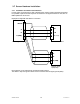
Components and Interfaces
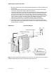
The diagram below illustrates which devices can be connected to the NAUTICAST. For a
detailed description of sensor connecting e.g. an existing Gyro to the NAUTICAST refer to
Chapter 3 “Sensor Installation” on page 12.
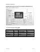
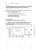
3.3 General Interface Description
Interface Designation Speed Direction
Sensor 1 CH 1 4800bps or 38400bps Input
Sensor 2 CH 2 4800bps or 38400bps Input
Sensor 3 CH 3 4800bps or 38400bps Input
ECDIS CH 4 38400bps Input/Output
PILOT CH 5 38400bps Input/Output
LONG RANGE CH 8 38400bps Input/Output
DGPS (RTCM SC104) CH 9 9600bps Input/Output
ALARM CIRCUIT CH 10 Dry relay contact (power off and alarm state closed)