
Specifications


Chapter 5 – Operational Guidelines
Section C. Performance Monitoring
C.1.
Performance
Monitoring
It is essential that the coxswain and crewmembers be aware of installed
monitoring equipment, gauges, and warning indicators, to ensure safe and
efficient operation of the RB-HS and RB-S propulsion and ancillary
systems. Crewmembers should be aware of the “normal range” or
indication of all gauges and indicators, and report and react accordingly
when changes occur.
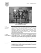
C.2. Control
Panel Indicators
The control panel (Figure 5-1 (RB-HS) and Figure 5-2 (RB-S)) is attached
to the dash panel, starboard side of the helm below the throttle controls.
The panel contains the following:
• Ignition switch
• Engine kill switch
• Alternator (ACG) indicator
• Programmed fuel injection (PGM-FI) indicator
• Oil pressure indicator
• Overheating indicator
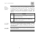
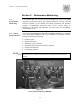
NOTE
Figure 5-1
Control Panel Indicators (RB-HS)
The RB-HS utilizes two separate control panels for engine start, stop, and monitoring.
The RB-S uses one control panel for both engines. Panel indicators and functions are
identical.
5-9