
Instruction manual

42
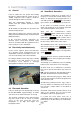
8. Fault Finding.
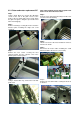
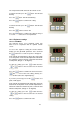
fig.11. Thermal cut-out
8.1 General
If the air curtain does not operate after running
through the detail provided in Section 6, then a
suitably competent service engineer should be
called to identify the nature of the fault.
Note The manufacturer operates a service
function from the address provided in these
instructions.
All Air Curtains are fitted with fuse protection and
motor thermal protection.
Other faults in relation to the element, motor and
wiring should be identified using conventional fault
finding techniques.
In the event that electrical components are
replaced, please ensure that electrical safety
checks in accordance with the regulations in force
in the country of use are undertaken.
8.2 Electrically heated units only.
For the service engineer, please note that there
are 2 thermal cut-outs incorporated in the air
curtain which need to be manually reset. The cut
-outs are located either side of the main PCB.
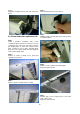
Re-setting a thermal cut-out may help to identify
the nature of the fault however we do not
recommend re-set without a thorough
investigation into why the cut-out operated.
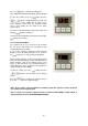
8.3 Electronic Controller.
If the air curtain goes into thermal trip (overheat)
the AC-ACR-PANEL keypad displays an ‘ERR’
code. Refer to air curtain instructions to remedy.
The electronic control base unit is protected from
any short circuit on the air sensor or heatsink
sensor as the short circuit will cause the
temperature to go high and trigger over
temperature alarm.
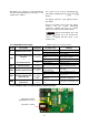
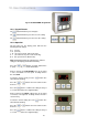
8.4 SmartElec2 Controllers.
The SmartElec2 control raises an alarm if any of
its inputs are outside their normal working scope.
Alarms are displayed on the program panel as a
code with a prefix "
E". The first number
represents the air curtain address. See chart over.
As the alarms are mutually exclusive, the first
alarm code displayed on the program panel will
stay on until the fault has been cleared.
Apart from the communication failure
alarm . which could be due to a broken
connection of the data link and air curtain not
found alarm, which could be due to
incorrect addressing, all other alarms will cause
the base unit to switch off the heater output.
The SmartElec2 base unit is protected from any
short circuit on the air sensor or heat
sink sensor as the error will cause the
temperature to rise and trigger over temperature
alarm.
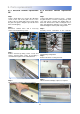
There are five basic checks to perform should
'X--'
appear on the program panel display.
These are as follows:
1: Continuity: Use a multimeter to check continuity
between each end of all four cores at the plugs
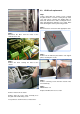
2: Short circuit: Use a multimeter to check that
there are no short circuits between any of the four
cores.
N.B. This test should be done with both ends of
the cable disconnected to avoid false readings.
3:
Plugs: Check that the plugs are firmly seated
on the circuit board pins in both the program panel
and on the base unit.
4:
Addressing: (Network versions only). If two or
more air curtains are networked, check that each
base unit has a unique address as described in
section 12.4
5: Network cables: Ensure that the total run of all
cables in the network does not exceed 110m
including the cable to the program panel.
If a panel has never before been run, it
automatically starts in engineer’s mode when first
powered-up. To exit this mode, press and hold the
Button.
0 E6
0 --
0 --
0 E1
0 E4
0 E1
E rr