
Instruction manual

37
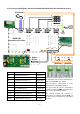
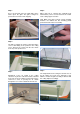
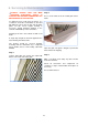
Fig.9 LPHW connections.
The LPHW copper tubing connections are as
shown in fig.9 above and are 15mm outside
diameter. Ensure correct water seal fittings are
used. We recommend the use of a suitable water
mains isolation valve to ease any maintenance.
Carefully close the grille and refit the fixing screw.
Test product as shown in the User Instructions.
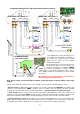
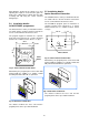
5.6.1 Three Port Valve
An optional 3 port valve (supplied by others) can be
used on the flow and return pipes to divert the hot
water from the unit when not in use.
The valve must be fitted in accordance with the
manufactures instructions.
When used in conjunction with the standard
AC-ACR programmer, the 3 port valve can be wired
into the base unit to open the valve when heat is
selected (see section 4.5). This valve must operate
on 230V.
Note: This option can not operate with a
SmartElec unit.
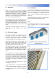
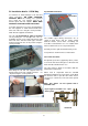
5.6 Installation details - LPHW Only
To avoid risk of transit damage to the flow and
return connections,
ON LPHW STANDARD
CAPACITY ONLY
the heating coil is provided
loose inside the case together with the air
deflector plate and side supports.
NOTE: HIGH
CAPACITY LPHW COILS ARE PRE-FITTED.
To install, unpack the loose items and identify the
two side supports as shown below and fit to the
inner side of the case using the screws provided.
Note The side supports are handed.
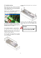
The coils
can be handed for right or left hand
exit by turning the coil through 180°. Prior to
installation decide if you require left hand or right
hand exit of the flow and return pipes from the
product and then fix the coil in position using the
screws provided.
After fitting the coil and side supports fit the air
deflector plate to the side supports and rotor cut
-off plate using the screws provided.
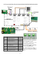
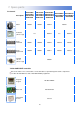
Fig.10 Typical schematic of a 3 port
valve system
AIRCURTAIN
RETURN
FLOW
Flow
connections