
Instruction manual

33
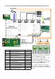
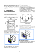
4.19 Network Wiring Electrically Heated with SmartElec2 Control.
COMMS
RS485
EXT
DOOR
STAT
TIMER
TEMP
COMMS
RS485
EXT
DOOR
STAT
TIMER
TEMP
BASE UNIT (air curtain '0')
BASE UNIT (air curtain '1')
To subsequent air curtains
(maximum of 16)
Switch**
Door
Sensor***
Optional
B.M.S.
Enable*
DOOR
J2
TIMER
J1
Switch**
Door
Sensor***
Optional
terminals as
supplied
PROGRAM PANEL
(rear view shown)
Pre-wired 4 core screened
cable and plugs
PCB mounted
connectors
(use either)
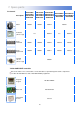
This diagram refers only to the wiring of 2 or
more networked air curtains. (maximum 16
air curtains per control panel). For mains
wiring refer to section 4 of this manual
‘installer wiring details’.
The program panel is connected to the base
unit in the air curtain via a pre-wired 4 core
screened cable/plugs to terminals ‘
COMMS
RS485’
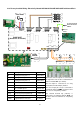
. These cables are available in 2, 10, 20, 30, 50 and
100m lengths. It is recommended that this control cable is
run separately within its own trunking to avoid external
interference.
Max cable run in any network must not exceed 110m in
total including program panel cable.
Note: All air curtains connected within the network system will operate under the settings of the single
keypad.
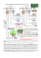
Any air curtain within the network can be connected with and respond to the following optional circuits:
* External switch (ie BMS enable) where required, to be volt free and wired in PARALLEL via normally open
contacts to each terminal pair
‘TIMER’. (Contacts closed to enable). Only air curtain(s) wired this way will
respond to the enable signal. Remove factory fitted jumpers J1.
(NOTE: terminals are polarity sensitive)
** Door switches where required, to be volt free and wired to INDIVIDUAL base units via normally closed
contacts to each terminal pair
‘DOOR’. (Contacts open to enable door mode). Only air curtain(s) wired this way
will respond to the door mode. Remove factory fitted jumper J2. refer section 10.2.6.1 - Door link settings.
*** Internal/external sensors, where required, to be wired to INDIVIDUAL base units to each terminal pair
‘EXT’. Only air curtain(s) wired this way will respond to the sensor setting. If a sensor is fitted to more than one
air curtain then the value is displayed as an average. refer section 10.2.6.4 - External temperature.