
Instruction manual

31
12
3N
N
HE
HE
HE
L1
L2
L3
EXT
DOOR
STAT
TIMER
TEMP
FAN
1
234
ON
BASE UNIT
(located in air curtain)
Fan motor
Sensor
Outlet
ϑ
Overheat
J1 J2
CHASSIS
EARTH
FACTORY
INSTALLED
EARTH LINK.
DO NOT REMOVE
ϑ
Overheat
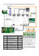
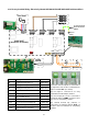
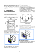
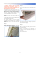
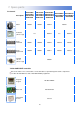
4.17 Factory Installed Wiring. Electrically Heated ACR100/ACR150 with SmartElec2 Control.
The heater element outputs are connected to
the right hand side of three terminal blocks
and are marked ‘
HE’. (See below).
The fan output is connected to a 4 way
terminal block marked ‘
N, 1, 2 and 3’.
The sensor input (air sensor) is connected to
2 terminals marked ‘
TEMP’ on the base unit.
The sensor is not polarity sensitive.
The external thermal trip (volt-free) is
connected to 2 terminals marked ‘
STAT’ on
the base unit. The terminals are not polarity
sensitive.
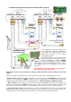
Terminal Description Cable
HE Heating elements phase 1 10mm² max
HE Heating elements phase 2 10mm² max
HE Heating elements phase 3 10mm² max
N Neutral to fan 1.5mm² max
1 Fan - low speed 1.5mm² max
2 Fan - medium speed 1.5mm² max
3 Fan - high speed 1.5mm² max
Temp Air sensor pair (non-polarised) 1.5mm² max
Stat Ext thermal trip pair, n.c. (volt-free) 1.5mm² max
Comms Keypad/network connectors Pre-wired