
Instruction manual


30
1
23N
N
HE
HE
HE
L1
L2
L3
COMMS
RS485
EXT
DOOR
STAT
TIMER
TEMP
FAN
12 34
ON
CHASSIS
EARTH
415v 50Hz
MAINS SUPPLY
BASE UNIT
(located in air curtain)
PROGRAM PANEL
(rear view shown)
Pre-wired 4 core
screened cable
and plugs
Switch**
Door
Sensor***
Optional
B.M.S.
Enable*
DOOR
TIMER
J2J1
terminals as
supplied
FACTORY INSTALLED
EARTH LINK. DO NOT
REMOVE
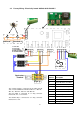
Terminal
Description Cable
N Neutral 10mm² max
L1 3 phase supply 10mm² max
L2 3 phase supply 10mm² max
L3 3 phase supply 10mm² max
E Mains earth 10mm² max
Timer* BMS pair (volt -free) 1.5mm² max
Door** Door interlock pair, n.c. (volt free) 1.5mm² max
Ext*** External sensor pair (non-polarised) 1.5mm² max
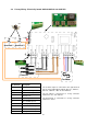
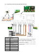
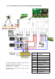
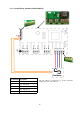
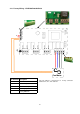
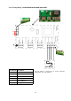
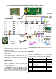
Interconnecting wiring
The program panel is connected to the base unit via
a set of pre-wired 4 core screened cables with pre
-wired plugs as shown.
Interconnecting wiring is via a 4 core screened cable
with pre-wired plugs, supplied in 2, 10, 20, 30, 50 and
100m lengths.
It is recommended that this control cable is run sep-
arately within its own trunking to avoid external inter-
ference.
Optional wiring
* External switch (ie BMS enable) to be volt free and
wired via normally open contacts to terminal pair
‘TIMER’. (Contacts closed to enable). Remove
factory fitted jumper J1.
** Door switch to be volt free and wired via normally
closed contacts to terminal pair
‘DOOR’. (Contacts
open to enable door mode). Remove factory fitted
jumper J2. refer section 10.2.6.1 - Door link settings.
4.16 Installer wiring diagram Electrically heated with SmartElec2 control.
*** Internal/external sensor to be wired to terminal pair
‘EXT’. refer section 10.2.6.4 - External Temperature.
Protection
There are two high speed fuses on the base unit to
protect the switching thyristors for the heater. An
external circuit breaker with the appropriate rating
should be installed for the protection of the installation.