
Instruction manual


29
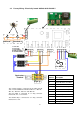
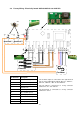
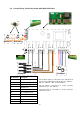
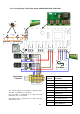
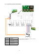
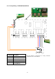
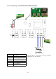
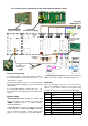
4.15 Network Wiring - Electronic controller
(rear view shown)
PROGRAM PANEL
To subsequent air curtains
(maximum of 6)
DATA
GND
+12V
DATA
GND
+12V
Screw terminals
(located in air curtain 1)
screen
2 core
screened
cable
T1
T2
B2
D2
S2
S1
D1
B1
AC1-T3
L3
AC2-T3
AC1-T2
L2
AC2-T2
External
Switch*
Remove link J1 for
external time switch
Door
Switch**
Sensor***
DATA
GND
+12V
(located in air curtain 2
T1
T2
B2
D2
S2
S1
D1
B1
AC1-T3
L3
AC2-T3
AC1-T2
L2
AC2-T2
DATA
GND
+12V
(located in air curtain 3)
T1
T2
B2
D2
S2
S1
D1
B1
AC1-T3
L3
AC2-T3
AC1-T2
L2
AC2-T2
External
Switch*
Door
Switch**
Sensor***
External
Switch*
Door
Switch**
Sensor***
Networking
This diagram refers only to the
wiring of 2 or more networked air
curtains. (maximum 6 air curtains
per control panel). For mains
wiring refer to section 4 of this
manual ‘installer wiring details’.
The program panel is connected
to the base unit in the
first air
curtain via a 2 core cable to a 3
way connector marked "+12V”,
“DATA” and “GND". The screen
being connected to “GND”.
Each subsequent air curtain is
wired via the “DATA” and “GND”
corresponding connections
only.
All interconnecting wiring is via
screened twisted pair 28AWG as
shown.
Max length 50m. (Total
length of cable used between
program panel and last air curtain
in network).
It is recommended that this control
cable is run separately within its
own trunking to avoid external
interference.
Note: All air curtains connected
within the network system will
operate in unison under the
user settings of the single
keypad.
Any air curtain can respond to
optional circuits i.e. *External
switch (BMS); or **Door switch
or ***Internal/external sensors
ON AN INDIVIDUAL BASES.