
Instruction manual


24
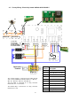
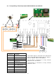
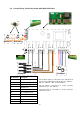
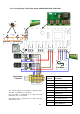
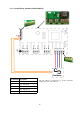
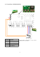
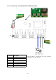
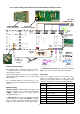
4.10 Factory Wiring - Electrically heated ACR200/ACR180HE 18kW 3Pha
The element outputs are connected to contactors "AC1”
and “AC2” on terminals T1, T2 and T3.
The fan output is connected to a 4 way connector
marked "N”, “F1”, “F2” and “F3".
The thermal trip is connected to a 2 way connector
marked "T1" & “T2”
Pcb
Terminal
Description
AC1/2-T1 Heater Elements phase 1
AC1/2-T2 Heater Elements phase 2
AC1/2-T3 Heater Elements phase 3
T1 Thermal Overheat trip
T2 Thermal Overheat trip
N Neutral to fan
F1 Fan - low speed
F2 Fan - medium speed
F3 Fan - high speed
J1 Factory BMS link
Fan Motor
Overheat
AC1-T3
T1
T2
B2
D2
S2
S1
D1
B1
DATA
GND
+12V
L3
AC2-T3
AC1-T2
L2
AC2-T2
AC1-T1
L1
AC2-T1
F1
F2
F3
N
N
Elements
AC1
T1
Contractors
Terminal
L1
T2
L2
T3
L3
A2
A1
Elements
AC2
T1 L1
T2 L 2
T3 L 3
A2 A1
J1
L1L2L3
N
E
X2
Overheat 2
J
Overheat 1