
Instruction manual

20
Fan Motor
AC1-T3
T1
T2
B2
D2
S2
S1
D1
B1
DATA
GND
+12V
L3
AC2-T3
AC1-T2
L2
AC2-T2
AC1-T1
L1
AC2-T1
F1
F2
F3
N
N
Elements
Contractors
Terminal
Elements
L(M)
R(M)
R(B)
L(B)
R(T)
L(T)
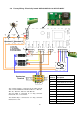
R= RIGHT SIDE
L= LEFT SIDE
T= TOP ELEMENT
M= MIDDLE ELEMENT
B= BOTTOM ELEMENT
LNE
Overheat 2
Overheat 1
J1
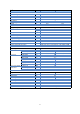
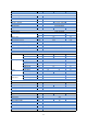
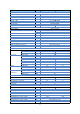
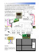
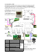
4.6 Factory Wiring - Electrically heated ACR100/ACR150 6 & 9kW 1Ph ONLY
The element output is connected to the right and left
side of each terminal block marked "AC1-T1”, “AC2-T1”,
AC1-T2”, “AC2-T2”, “AC1-T3” and “AC2-T3”
The fan output is connected to a 4 way connector
marked "N”, “F1”, “F2” and “F3".
The thermal trip is connected to a 2 way connector
marked "T1" & “T2”
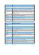
X2
Pcb
Terminal
Description
L1 Heater Elements one third
L2 Heater Elements one third
L3 Heater Elements one third
T1 Thermal Overheat trip
T2 Thermal Overheat trip
N Neutrals
F1 Fan - low speed
F2 Fan - medium speed
F3 Fan - high speed
J1 Factory BMS link