
Instruction manual

18
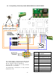
T1
T2
B2
D2
S2
S1
D1
B1
DATA
GND
+12V
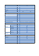
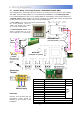
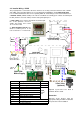
BASE UNIT
(located in air curtain)
230V 50Hz
Mains Supply
Chassis
Earth
PROGRAM PANEL
(rear view shown)
External
Switch
J1
Remove link J1 for
external time switch
DATA
GND
+12V
F1
F2
F3
N
N
AC1-T3
L3
AC2-T3
AC1-T2
L2
AC2-T2
AC1-T1
L1
AC2-T1
Door
Switch
screen
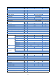
Pcb Terminal Description Cable
N Neutral 4mm² max
L 1 phase supply 4mm² max
+12V Supply to remote unit
DATA Data to remote unit
GND(s) 0v Terminal
D1, D2 Option door contact**
B1, B2 Option External switch*
Pcb Fuses Rating (A)
F1 T2A (slow blow)
F2 T3.15A (slow blow)
Cable
1.0mm
2
max
Protection
External circuit breaker with the appropriate
rating should be installed for the protection
of the installation.
4.4 Installer Wiring - Ambient
The program panel is connected to the base unit via a set of 3 way connectors marked "+12V”, “DATA”
and “GND". Interconnecting wiring is via screened twisted pair 28AWG as shown.
Max length 50m.
It is recommended that this cable is run separately within its own trunking to avoid external interference.
* External switch (ie BMS enable) to be volt free and wired
via normally open contacts to terminal pair B1, B2. (Contacts
closed to enable). Remove factory fitted jumper J1.
** Door switch to be volt free and
wired via terminal pair D1 & D2
(Contacts closed to enable door
mode) refer section 10.1.3.2 - Door
switch mode.
F1
F2
*
**