
User Manual

Y1-03-0180 Rev. T1
10
Attach male SMA connector (supplied) to coax cable per included instructions. Connect to
mating female SMA connector on the beacon.
SECTION 4 - OPERATION
4.1 General
4.1.1 The ThunderBird S.S.A.S. Beacon is designed to be manually activated while installed in the
mounting bracket. In fact, the ThunderBird S.S.A.S. beacon can only be activated manually.
4.1.2 The following two conditions must be satisfied to activate the ThunderBird S.S.A.S.:
1) The switch on the beacon must be placed in the “READY” position.
2) One of the remote activation switches must be depressed.
4.1.3 The ThunderBird S.S.A.S. is designed to allow the user to perform periodic testing while
S.S.A.S is in the mounting bracket to assure a functioning beacon.
4.2 Controls
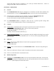
4.2.1 Thumb Switch: The thumb switch on the top left part of the beacon controls the mode of
operation of the ThunderBird S.S.A.S. There are three switch positions:
1) Off: Down to the front, indicated by “O”
2) Self-Test: Vertical
3) Ready: Down to the back, indicated by “│”
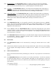
4.2.2 Remote Activation Switches: These are momentary switches installed on the ship that are used to
activate the beacon when placed in READY mode. To activate, lift the spring-loaded guard and
press the button.
4.3 Indicators
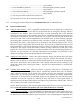
4.3.1 LED’s: There are two LED indicators located on the top right part of the beacon:
1) TEST LED: Green
2) XMIT LED: Red
4.3.2 Buzzer:
There is an internal buzzer in the ThunderBird S.S.A.S. The buzzer beeps during the
Self-Test.
4.3.3 There are no indicators of beacon’s mode of operation at the remote activation points.
4.3.4 There is no audio indication of transmission mode.
4.4 Modes of Operation
4.4.1 OFF Mode:
The ThunderBird S.S.A.S. can not be activated when in OFF mode. The beacon is
in OFF mode whenever the thumb switch is in the “Off” position (down to the front) as indicated
by the “O” symbol displayed on the thumb switch.