
User Manual
Y1-03-0180 Rev. T1
9
If the supplied bracket is not ideal for the desired mounting location, the cross dipole has a
standard female 1” x 14 thread allowing it to be mounted to a variety of off-the-shelf brackets and
masts (Not provided).
3.3.2 Mounting Guidelines
• Minimum height above deck: 10 feet
• Allowable obstructions: Obstructions are allowable only below the antenna.
There should be no conductive (metallic) objects in
the entire hemisphere above the antenna.
• 100 feet (30.48 m) of RG-8U coaxial cable is supplied with each ThunderBird S.S.A.S.
Appropriate connectors are also supplied. Contact the factory if longer runs or different
coaxial cable is required.
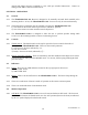
3.3.3 Antenna Assembly
The antenna is shipped with the four elements removed from the housing. Before using the
antenna, these elements must be assembled to the antenna housing.
For each element, assemble as follows:
• Slide the element into a hole in the side of the housing until it stops
• Tighten appropriate set screw through hole in the bottom housing using included wrench
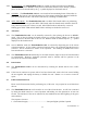
3.3.4 Antenna Installation
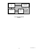
Select mounting location using guidelines and general information above. The top of a mast is an
ideal location for the cross dipole. Mounting to an existing spar or to a bracket attached to a mast
is also acceptable. See Figure 7 for examples. The antenna must be mounted with the connector
pointing down and the elements horizontal. If mounting on a spar or bracket, the antenna
elements must be oriented approximately 45° to the horizontal support when looking from the top
or bottom, as shown in Figure 7.
Use one of the following methods to mount the antenna per the guidelines and general
information above with all four elements in the horizontal plane:
• The included mount can be used to attach to any small, flat, horizontal surface; i.e. the
top of a mast or a spar. In this case drill holes in the pattern of the mount and attach with
screws as needed.
• The included mount can be used to attach the antenna to a round spar using U-bolts.
• The antenna can be mounted to any bracket or mast with the standard 1” x 14 thread.
3.3.5 Connection to Beacon
Attach male TNC connector (supplied) to coax cable per included instructions. Connect to mating
female TNC connector on antenna.
Route cable to SSAS beacon as needed, making sure to adequately secure the cable. Provide a
drip loop in the cable near the beacon to prevent water from running directly on to the beacon.