
User Manual
Y1-03-0180 Rev. T1
8
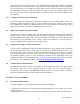
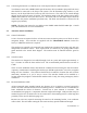
3.2.4 Switch Installation
Cut a 0.638” x 0.638” (16.2 mm x 16.2 mm) square hole in the selected panel. The recommended
panel thickness is 0.039” to 0.106” (1.0 mm to 3.2 mm).
Connect the wires to the back of the switch; one wire to “COM” terminal and the other to “N.O.”
terminal. There should be no connection to the “N.C.” terminal. The wires should be soldered to
the switch terminals. Once the connections are made, make sure the spring-loaded switch guard is
securely attached to the switch and press the switch assembly into the panel hole. The switch will
snap into place.
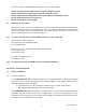
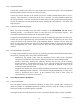
3.2.5 Connection to Mounting Bracket
Route the switch wire/cables from the switch locations to the ThunderBird S.S.A.S. beacon
mounting bracket. Care should be taken to route and secure the wire/cables properly. The
wires/cables should then be trimmed to the appropriate length.
If using the recommended 16 to 22 AWG wire, crimp the terminal lugs (provided) onto the wires.
If other wire is used, appropriate lugs (Not provided) can be used. Alternatively, the wire can be
connected directly to the terminal block on the mounting bracket. Connect one wire from each
switch to one of the two terminals on the top of the mounting bracket by placing the lug under the
screw and tightening the screw. Repeat with the other wire from each switch in the other
terminal.
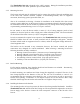
3.2.6 Switch Installation Verification
To verify proper installation of the switches, the following procedure should be followed (requires
two persons, preferably with 2-way radio communications):
• Disconnect the beacon cable from the mounting bracket cable (2-pin waterproof
connector on the left side of the beacon), leaving the beacon in the mounting bracket.
• With a multi-meter, measure the resistance between the two pins on the mounting
bracket connector. This should be an open. If not, check the switch wire connections to
make sure the two wires from each switch are connected to different screws on the
mounting bracket terminal block.
• Depress each switch (one at a time) while measuring the resistance between the two pins
on the mounting bracket connector. The resistance should momentarily (as long as the
switch is depressed) read a short. If the resistance never reads a short, verify all
connections are per 3.2.4 and 3.2.5 above.
3.3 Cross Dipole Antenna Installation
3.3.1 General Information
The cross dipole antenna is intended for operation far away from a ground plane. With this in
mind, the location of installation should be carefully selected to keep the antenna as far from
horizontal conductive (metallic) planes as possible.
The length of cable from the SSAS beacon to the cross dipole should be kept as short as possible.