
Instruction Manual


ACR ELECTRONICS, INC / ARTEX PRODUCTS
DESCRIPTION, OPERATION, INSTALLATION AND MAINTENANCE MANUAL
C406-2 (453-5000), C406-2HM (453-5001)
25-62-11
Page 56 of 87
JUN 20/13
SUBTASK 25-62-11-450-002
B. Installation
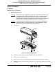
(1) See Figure 14.
Figure 14 Typical Mounting Tray Installation
(2) Install the necessary mounting structure as appropriate for the specific installation.
(3) Align the mounting tray (452-5050) on the mounting structure, such that the arrow on the
tray is within 10° of the longitudinal axis of the aircraft and pointing in the direction of flight.
NOTE
: Refer to TASK 25-62-11-410-803 on page 76 for guidelines on ELT orientation in a
helicopter.
(4) Mark the four holes needed for mounting the tray, using the tray as a pattern. The hole
pattern is also illustrated in "Figure 13 C406-2 Series ELT Outline and Dimensions” on
page 56.
(5) Drill the four mounting holes with a #19 or 4.25 mm drill.
(6) Install the mounting tray with the 8-32 x 5/8” SS pan head phillips screws, flat washers, lock
washers, and nuts provided in the installation kit (455-7421), as shown in "Figure 14 Typical
Mounting Tray Installation” on page 57.
NOTE
: The use of substitute mounting hardware is acceptable provided the hardware used
meets or exceeds the strength and corrosion resistance of the original hardware.
(a) Torque to 12 ±1 lb-in (136 ± 11 N•cm).
8-32 x 5/8 SCREW
(4 PLCS)
#8 FLAT WASHER
(4 PLCS)
#8 LOCK WASHER
(4 PLCS)
8-32 X 1/4 HEX NUT
(4 PLCS)
AIRFRAME
STRUCTURE (REF.)
EQUIPMENT MOUNTING
PLATE (REF.)
MOUNTING
TRAY