X-FIRES 600-750 Designer Flueless Fires INSTALLATION & USERS INSTRUCTIONS X-FIRE 600 Product Codes HIW-XF20 - Limestone model HIW-XF21 - Granite model X-FIRE 750 Product Codes HIW-XF22 - Limestone model HIW-XF23 - Granite model Leave with the User Revision B - 03/12 Acquisitions of London 24-26 Holmes Road London NW5 3AB Tel: 0044 (0)207 482 2949 Email: sales@acquisitions.co.uk Country(s) of destination : GB, IE Product Identification No.
600 750 The products covered by this booklet are protected under patents GB2275331B, GB2429186B and GB2413178B. Please note : Except where otherwise stated, all rights, including copyright in the text, images and layout of this booklet is owned by Acquisitions of London. You are not permitted to copy or adapt any of the content without the prior written permission of Acquisitions of London.
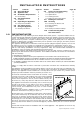
INSTALLATION INSTRUCTIONS Section Contents 8.0 Testing and Commissioning 8.1 Operating the Appliance 8.2 Spark Failure 8.3 Setting pressure 8.4 Fitting the Decorative Frame 9.0 Briefing the customer 10.0 Servicing 10.1 Servicing the Burner Unit 10.2 Pilot Assembly 10.3 Catalyst 10.4 Testing for Firebox Leakage 11.0 Troubleshooting Guide User Instructions Section Contents Page No. 1.0 Important Notes 1 2.0 Appliance Data 2 3.0 Installation Requirements 2 3.1 Room Sizing 2 4.0 Site Requirements 2 4.
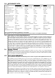
2.0 APPLIANCE DATA 600 Natural gas 600 LPG 750 Natural gas 750 LPG Gas Group G20 Natural Gas CAT I2H G31 Propane CAT I3P G20 Natural Gas CAT I2H G31 Propane CAT I3P Inlet/Operating Pressure 20 mbar (± 2.0mbar) 37 mbar (± 2.0mbar) 20 mbar (± 2.0mbar) 37 mbar (± 2.0mbar) Regulator Pressure N/A 24.5 mbar N/A 24.5 mbar Max Energy Input (Gross) 2.0 kW 1.7 kW 2.0 kW 1.7 kW Max Energy Input (Net) 1.8 kW 1.56 kW 1.8 kW 1.56 kW Max Gas Rate 0.20 m3/h 0.065 m3/h 0.20 m3/h 0.
4.0 SITE REQUIREMENTS (continued) Clearances to non-combustibles Non combustible surfaces are defined as brick, metal, marble, concrete etc. and also a number of man-made materials impervious to flame. If in doubt refer to the material manufacturer for further information before proceeding with installation. Clearances to the sides of the appliance are 100mm (4”). Clearance to the front of the appliance is 500mm (20”).
5.0 UNPACKING THE APPLIANCE Remove the outer packaging, remove any instructions or fixing kits. Read ALL these instructions before continuing to unpack or install this appliance. Lift off the remaining packaging components and remove the contents of the box. Check that the components supplied correlate with the component checklist. Please dispose of all the packaging materials at your local recycling centre. 5.1 COMPONENT CHECKLIST QUANTITY 1 1 1 1 1 1 6.
.0 FIXING THE APPLIANCE (continued) If the appliance is to be mounted on the inner leaf of a conventional cavity brick wall, or a solid wall, then the wall plugs and fixing screws provided may be used. Depending on the condition of the wall it may be necessary to use additional fixings. In this situation, any additional fixings and wallplugs should be of the same size and type as the ones provided. At the appropriate stage of the installation, drill four holes using only a 8.
.0 TESTING AND COMMISSIONING Turn on and test the gas supply up to the fire for any leaks, in accordance with the current edition of BS 6891 (natural gas installations) or the current edition of BS 5482 pt1 (propane installations). 8.1 OPERATING THE APPLIANCE The control knob is located on the lower right hand side of the ‘OFF’ position outer case. It is marked as shown in figure 7. The pilot is visible behind the left hand side of the burner.
8.4 FITTING THE DECORATIVE FRAME ASSEMBLY All models : Remove any protective packaging, and remove any protective film that may be present on the frame. 2mm Figure 9 The facia panel is supported by four M6 screws which protrude from the front of the outer casing. Ensure each screw is unscrewed approximately one turn from the fully screwed in position in order to create a 2mm gap (see figure 9).
.1 SERVICING THE BURNER UNIT AND GAS ASSEMBLY (continued) Remove the pilot and main burner pipes and blow through to dislodge any debris. Now remove the restrictor elbow and blow through to make sure it is entirely clear. Unclip the pilot lint gauze and clean with a soft brush. Clean the exterior of the pilot assembly with a soft brush and blow through the flame ports on the pilot head. Check the aeration holes are free from lint or dirt.
.0 TROUBLESHOOTING GUIDE Fire sparks but pilot does not light No gas to fire, check isolators are open. Pipe work blockage, clean out. Air not fully purged, re purge supply or wait longer. Spark earthing to metal work, reset gap correctly. Blocked pilot, clean out internally. Pilot lights but then goes out Severe restriction in gas supply: clear obstruction. Faulty thermocouple, replace pilot unit. Blocked pilot, clean out. Blocked lint gauze, clean. Hold control knob in for longer.
U S E R Section 1.0 2.0 3.0 4.0 5.0 6.0 7.0 8.0 1.
2.0 CLEARANCES TO COMBUSTIBLES Clearances to non-combustibles Non combustible surfaces are defined as brick, metal, marble, concrete etc. and also a number of manmade materials impervious to flame. If in doubt refer to the material manufacturer for further information before proceeding with installation. Clearances to the sides of the appliance are 100mm (4”). Clearance to the front of the appliance is 500mm (20”).
3.0 VENTILATION AND ROOM SIZE (continued) The room size should be a minimum of 23m3 (e.g. 10’1” x 10’1” x 8’) to allow adequate circulation of air and ensure the correct operation of the fire. This volume may include adjacent spaces but these spaces must not be separated by a door. To calculate a room size in cubic metres (m3) divide the room volume in cubic feet (ft3) by 35.3.