
Installation guide


Chapter 3
Chassis Hardware
3 - 6
• Fan speed controlled by SCM in response to temperature fluctuations in
the chassis
• Fan tachometer monitors revolutions per minute (RPM)
• Closed-loop system monitors temperature conditions in the chassis with
a return to the fan system; this causes airflow to increase or decrease, as
required, to maintain the proper temperature within the chassis
• Two LEDs on the fan-tray front panel indicate operational status (see
Chapter 8,
Maintenance for LED descriptions)
• Failure indications include:
• Single fan failure
• Multiple fan failure
• Low/high RPM on any fan
• High temperature
• Lost SCM-to-fan tray communication
Chassis Configurations
The ARX
®
6000 can accommodate up to six modules in its chassis, and these
modules can be configured to maximize throughput or to maximize high
availability between switches.
The switch currently supports one management module (SCM) in slot 1 and
service modules (NSM and ASM) in any order (or combination) in the
service module slots. Most configurations require at least one NSM for
network connectivity and one ASM for adaptive services. See Chapter 4,
Hardware Modules for information about the individual ARX
®
6000
modules.
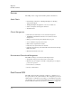
Table 3.1
describes the basic and maximum capacity ARX
®
6000 chassis
configurations.
Basic System Maximum Capacity
Slot Module Slot Module
1
SCM
a
1SCM
2
Service Modules
b
2 ASM
3 3 ASM
4 4 ASM
55NSM
66NSM
Table 3.1 ARX
®
6000 Chassis Configurations