
Installation guide


Chassis Components
ARX
®
6000 Hardware Installation Guide 3 - 5
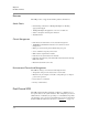
The disk drives are connected through a SCSI bus to the System Control
Module (SCM) in the chassis. The dual-channel SCM communicates over
two separate buses to the disk drives in bay shelves D1 and D2. Figure 3.3
shows the SCM-to-drive interconnections.
Figure 3.3 Dual-Channel Internal Drive Connections
Logical Unit Numbers (LUNs)
Each system drive has a logical unit number (LUN) (address 1 and 2)
corresponding to bay slot 1 (D1) and bay slot 2 (D2). Dual-channel drives
are mapped to LUNs 1 and 2. LUNs enable multiple drives to be
“daisy-chained” to a single controller. The LUN address identifies the drive
so that the controller can send the correct data to the correct drive(s).
Status LEDs
The disk drives provide three status LEDs:
• Red — indicates Activity
• Green — indicates Power
• Orange — indicates Failure
Fan Tray Module
The chassis fan tray module is an environmentally controlled fan system
with an intelligent fan controller. The fan tray contains six individual fans
and is located at the top of the chassis (refer back to in Figure 3.1 on
page 3-3).
The “hot-pluggable” fan tray (containing six fans) is a field replaceable unit
(FRU) that can be replaced without service interruption. See Appendix B,
<Emphasis>Removing and Replacing FRUs for information about
removing/replacing FRUs.
The SCM has redundant connections to the fan tray module for temperature
control and status monitoring. It communicates with the fan tray module at
regular 60-second intervals.
Features
The fan tray module provides the following features:
• Fan speed controlled through a pulse modulated input to the fan
SCM
Backplane
SCSI
Controller
A
B
Shelf D1
Shelf D2
Disk 1
Disk 2