
User's Manual


1010
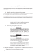
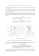
Table 2-2
RS 232
interface
PIN
NO.
PIN NAME DESCRIPTION SPECIFICATIONS
Rear panel
view
1 - Not connected -
2 TxD Transmitted Data RS232 level output
3 RxD Received Data RS232 level input
4 - Not connected -
5 GND Ground 0 Volt
6 DSR Remote Power On RS232 level input
7 - Not connected -
8 CTS Remote Power On RS232 level input
9 - Not connected -
3. INITIAL POWER ON AND OPERATION
C A U T I O N
Do not turn the amplier on at least two hours after unpacking it
and installing in its nal operating position. Pay special attention
whenever the amplier is moved from a very cold place to a very
warm one because condensation may develop on the inside
resulting in damage to the high voltage circuits of the amplier.
Under these circumstances, do not turn the amplier on for at least
4 hours. A similar effect could occur following a rapid warming of
the room, such as winter usage of a powerful electric heater.
After following all instructions in Section 2 INSTALLATION, check whether the rear panel mains switch
is turned off. Then plug the amplier in the mains outlet.
3-1.
Low energy standby mode of the power supply
Now you can turn on the mains switch on the rear panel. This will activate only the low-energy stand-by
mode of the amplier power supply and will light up the red LED above POWER button, while the main
power supply is still off and the display is dark.
3-2.
Front panel - controls and readouts
a) POWER button. When the rear panel mains switch is turned on, push and hold 1-2 seconds to
start the amplier up. When the amplier is turned on, push to turn it off (back to standby mode).
b) LED indicator above the POWER button. When lit red and the screen is dark, the amplier is in
standby mode and may be turned on by pushing the POWER button.