RMC 7150 14” short depth rack server User Manual RMC 7150: 14” short depth server with two Intel Xeon processors 1 14628 Central Blvd, Chino, CA91710 tel:909.597.7588, fax:909.597.1939 © Copyright 2011 Acnodes, Inc. All rights reserved. Product description and product specifications are subject to change without notice. For latest product information, please visit Acnodes’ web site at www.acnodes.com.
RMC 7150 14” short depth rack server PC 5150 15-inch touch panel PC ABOUT THIS MANUAL: The information in this User’s Manual has been carefully reviewed and is believed to be accurate. The vendor assumes no responsibility for any inaccuracles that may be contained in this document, makes no commitment to update or to keep current the information in this manual, or to notify that person or organization of the updates.
RMC 7150 14” short depth rack server Manual Organization Chapter 1: Introduction The first chapter provides a checklist of the main components included with the server system and describes the main features of the RMC 7150 and its chassis. Chapter 2: Server Installation This chapter describes the steps necessary to install the RMC 7150 into a rack and check out the server configuration prior to powering up the system.
RMC 7150 14” short depth rack server PC 5150 15-inch touch panel PC CHAPTER 1 1.1 Overview The Acnodes Crop RMC 7150 is a 1U rackmount server designed for optimal space efficiency. It is comprised of two main subsystems: the RMC 7150 1U chassis and the serverboard. Please refer to our web site for information on operating systems that have been certified for use.
RMC 7150 14” short depth rack server 1.2 Serverboard Features It is a dual processor serverboard based upon Intel’s 5500 +ICH10R chipset. Below are the main features of the processor. Processor It supports a single or dual two Intel 5500 Series processors in LGA1366 sockets. Memory Slots can support up to 24 GB of ECC. Serial ATA An on chip SATA controller is integrated to provide a six-port, 3Gb/sec SATA subsystem, which is RAID 0, 1, 5 and 10 supported. The SATA drives are hot-swappable units.
RMC 7150 14” short depth rack server PC 5150 15-inch touch panel PC 6 14628 Central Blvd, Chino, CA91710 tel:909.597.7588, fax:909.597.1939 © Copyright 2011 Acnodes, Inc. All rights reserved. Product description and product specifications are subject to change without notice. For latest product information, please visit Acnodes’ web site at www.acnodes.com.
RMC 7150 14” short depth rack server 1.4 Contacting Acnodes HEADQUARTERS Address: Acnodes Corp. 661 Brea Canyon Rd. Walnut, CA 91789 Tel: (909) 598-7388 Fax: (909) 598-0218 Email: info@acnodes.com Website: www.acnodes.com 7 14628 Central Blvd, Chino, CA91710 tel:909.597.7588, fax:909.597.1939 © Copyright 2011 Acnodes, Inc. All rights reserved. Product description and product specifications are subject to change without notice. For latest product information, please visit Acnodes’ web site at www.
RMC 7150 14” short depth rack server PC 5150 CHAPTER 2 15-inch touch panel PC 2.1 Overview This chapter provides a quick setup checklist to get your RMC 7150 up and running. FOllowing the steps in the order given should enable you to have the system operational within a minimal amount of time. This quick setup assumes that your system has come to you with the processor and memory preinstalled. If your system is not already fully integrated with a serverboard, processor, system memory etc.
RMC 7150 14” short depth rack server 2.4 Installing the System into a Rack This section provdes information on installing the RMC 7150 into a rack unit. If the sysetm has already been mounted into a rack, you can skip ahead to sections 2-5 and 2-6. Basic Installation Procedure The RMC 7150 server comes with two rack mounting brackets, which are located on each side at the front of the chassis.
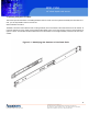
RMC 7150 14” short depth rack server PC 5150 Installing with Rackmount Kit 15-inch touch panel PC This is a guideline for installing the unit into a rack with the optional rack kit. You should also refer to the Installation Instructions that came with the rack unit you are using. Be aware that there are a variety of rack units on the market, which may mean the assembly procedure will differ slightly.
RMC 7150 14” short depth rack server 2.1 USB 1/2 Connector 1. Determine where you want to place the RMC 7150 in the rack. 2. Position the fixed rack rail/sliding rail guide assemblies at the desired location in the rack, keeping the sliding rail guide facing the inside of the rack. 3. Screw the assembly securely to the rack using the brackets provided. 4. Attatch the other assemble to the other side of the rack, making sure that both are at the exact same height and with the rail guides facing inward.
RMC 7150 14” short depth rack server PC 5150 Installing the Server into a Telco Rack 15-inch touch panel PC If you are installing the RMC 7150 into a Telco type rack, follow the directions given on the previous pages for rack installation. The only difference in the installation procedure will be the positioning of the rack brackets to the rack. They should be spaced apart just enough to accomodate the width of the telco rack. 12 14628 Central Blvd, Chino, CA91710 tel:909.597.7588, fax:909.597.
RMC 7150 14” short depth rack server 2.5 Checking the Serverboard Setup After you install the server in the rack, you will need to open the unit to make sure the serverboard is properly installed and all the connections have been made. Removing the Chassis Cover 1. Release the retention screws that secure the unit to the rack. 2. Grasp the two handles on either side and pull the unit straight out until it locks (you will hear a “click”) 3.
RMC 7150 14” short depth rack server PC 5150 15-inch touch panel PC 14 14628 Central Blvd, Chino, CA91710 tel:909.597.7588, fax:909.597.1939 © Copyright 2011 Acnodes, Inc. All rights reserved. Product description and product specifications are subject to change without notice. For latest product information, please visit Acnodes’ web site at www.acnodes.com.
RMC 7150 14” short depth rack server CHAPTER 3 SYSTEM INTERFACE 3.1 Overview There are several LEDs on the control panel to keep you constantly informed of the overall status of the system as well as the activity and health of specific components. There are also two buttons on the chassis control panel. This chapter explains the meanings of all LED indicators and the appropriate respnse you may need to take. 3.
RMC 7150 14” short depth rack server PC 5150 3.3 Control Panel LEDs 15-inch touch panel PC The control panel located on the front of the RMC 7150 chassis has five LEDs. These LEDs provide you with critical information related to different parts of the system. This section explains what each LED indicates when illuminated and any corrective action you may need to take. Overheat/Fan Fail When this LED flashes it indicates a fan failure.
RMC 7150 14” short depth rack server CHAPTER 4 SYSTEM SAFETY 4.1 Electrical Safety Precautions Basic electrical safety precautions should be followed to protect yourself from harm and the RMC 7150 damage: - Be aware of the locations of the power on/off switch on the chassis as well as the room’s emergency power on/off switch, disconnection switch or electrical outlet. If an electrical accident occurs, you can then quickly remove power from the system.
RMC 7150 14” short depth rack server PC 5150 CHAPTER 4 SYSTEM SAFETY 15-inch touch panel PC 4.3 ESD Precautions Electrostatic Discharge (ESD) is generated by two objects with different electrical charges coming into contact with each other. An electrical discharge is created to neutralize this difference, which can damage electronic components and printed circuit boards.
RMC 7150 14” short depth rack server CHAPTER 5 ADVANCED SERVERBOARD SETUP This chapter covers the steps required to install the serverboard into the chassis. Connect the data and power cables and install add-on cards. All serverboard jumper and connections are also described. A layout and quick reference chart are included in this chapter for your reference. Remember to completely close the chassis when you have finished working with the serverboard to better cool and protect the system. 5.
RMC 7150 14” short depth rack server PC 5150 5.3 Connecting Cables 15-inch touch panel PC Now that the serverboard is installed, the next step is to connect the cables to the board. These include the data cables for the peripherals and control panel and the power cables. Connecting Data Cables The cables used to transfer data from the peripheral devices have been carefully routed to prevent them from blocking the flow of cooling air that moves through the system from the back.
RMC 7150 14” short depth rack server 5.4 Rear I/O Ports The I/O ports are color coded in conformance with the PC 99 specification. 21 14628 Central Blvd, Chino, CA91710 tel:909.597.7588, fax:909.597.1939 © Copyright 2011 Acnodes, Inc. All rights reserved. Product description and product specifications are subject to change without notice. For latest product information, please visit Acnodes’ web site at www.acnodes.com.
RMC 7150 14” short depth rack server PC 5150 5.5 Installing the Processor and Heatsink 15-inch touch panel PC When handling the processor package, acoide placing direct pressure on the label area of the fan. Notes: - Always connect the power cord last and always remove it before adding, removing or changing any hardware components. Make sure that you install the processor into the CPU socket before you install the CPU heatsink.
RMC 7150 14” short depth rack server 1. After removing the plastic cap, use your thumb and the index finger to hold the CPU at the north and south center edges. 2. Align the CPU key (the semi-circle cutout) with the socket key (the notch below the gold color dot on the side of the socket). 3. once the CPU and the socket are aligned, carefully lower the CPU straight down into the socket. Do not rub the CPU against the surface of the socket or its pins to avoid damaging the CPU or the socket. 4.
RMC 7150 14” short depth rack server PC 5150 Installing a Passive CPU Heatsink 15-inch touch panel PC 1. Place the heatsink on top of the CPU so that the four mounting holes are aligned with those on the retention mechanism. 2. Install two diagonal screw and tighten them until just snug. 3. Repeat steps 2 with the #3 and #4 screws. Make sure all screws are snug. 24 14628 Central Blvd, Chino, CA91710 tel:909.597.7588, fax:909.597.1939 © Copyright 2011 Acnodes, Inc. All rights reserved.
RMC 7150 14” short depth rack server Removing the Heatsink 1. Power down the system and unplug the power cord from the power supply. 2. Disconnect the heatsink fan’s wires from the fan header. 3. Using a screwdriver, loosen and remove the heatsink screws from the serverboard in the sequence as shows in the previous section (#1 and #2 followed by #3 and #4. 4. Hold the heatsink as showin in the picture on the right and gently wiggle it to loosen it from the CPU. 5.
RMC 7150 14” short depth rack server PC 5150 5.6 Installing Memory Modules 15-inch touch panel PC 1. Insert the desired number of DIMMs into the memory slots, starting with DIMM #1A. For best performance, please use the memory modules of the same type and same speed in the same bank. See the DIMM Installation Chart on the following page. 2. Press down the release tabs on the ends of a memory slot. Insert each DIMM module vertically into its slot.
RMC 7150 14” short depth rack server Memory Support It supports up to 24 GB Registered ECC DDR3-1333/1066/800 MHz registered ECC SDRAM in 6 DIMM slots. DIMM sizes of 4GB, 2GB, and 1GB are supported. Populating DIMMs Follow the tables below when installing memory. 27 14628 Central Blvd, Chino, CA91710 tel:909.597.7588, fax:909.597.1939 © Copyright 2011 Acnodes, Inc. All rights reserved. Product description and product specifications are subject to change without notice.
RMC 7150 14” short depth rack server PC 5150 15-inch touch panel PC 5.7 Adding PCI Cards It includes a riser card. This riser fits into a PCI slot to support a full-height, half-length PCI Express expansion card. (THe riser card provides a PCI-E x 8 signal.) PCI Card Installation When installing a PCI add-on card, make sure you install it into a slot that supports the speed of the card. 1. Swing the release tab on the PCI slot shield. 2.
RMC 7150 14” short depth rack server 5.8 Serverboard Details Serverboard Layout 29 14628 Central Blvd, Chino, CA91710 tel:909.597.7588, fax:909.597.1939 © Copyright 2011 Acnodes, Inc. All rights reserved. Product description and product specifications are subject to change without notice. For latest product information, please visit Acnodes’ web site at www.acnodes.com.
RMC 7150 14” short depth rack server PC 5150 5.9 Connector Definitions 15-inch touch panel PC ATX Power Connector The primary power supply connector meets the SSI EPS 12V specification. Refer to the table on the right for the pin definitions of the ATX 14-pin power connector. You must also connect the 8-pin processor power connectors to your power supply. Processor Power Connector In addition to JPW1, the 12V 8-pin processor power connectors at JPW2 and JPW3 must be connected to your serverboard.
RMC 7150 14” short depth rack server Power Fail LED The Power Fail LED Connection is located on pins 5 and 6. Refer to the table on the right for pin definitions. Overheat LED (OH) Conneect an LED to the OH connection on pins 7 and 8 of JF1 to provide advanced warning of chassis overheating. Refer to the table on the right for pin definitions. NIC2 (LAN2) LED The LED Connections for LAN2 are on pins 9 and 10 of JF1. Attatch LAN LED cables to display network activity.
RMC 7150 14” short depth rack server PC 5150 Power on LED 15-inch touch panel PC The Power On LED connector is located on pins 15 and 16 of JF1. This connection is used to provide LED indication of power being supplied to the system. See the table on the right for pin definitions. NMI Button The non-maskable interrupt button header is located on pins 19 and 20 of JF1. Refer to the table on the right for pin definitons. Fan Headers There are six fan headers.
RMC 7150 14” short depth rack server Universal Serial Bus (USB) There are two Universal Serial Bus ports located on the I/O panel and five additional USB headers located on the serverboard. The headers labeled USB 2/3 and USB 4/5 can be used to provide front side USB acc ess (cables not included). USB 6 is an A type. See the tables on the right for pin definitions.
RMC 7150 14” short depth rack server PC 5150 Onboard Speaker (SP1) 15-inch touch panel PC The onboard speaker provides audible indications for carious beep codes. See the table on the right for pin definitions. Power LED/Speaker On the JD1 header, pins 1-3 are for a power LED and pins 4-7 are for the speaker. See the table on the right for speaker pin definitions. Note: The speaker connector pins are for use with an external speaker.
RMC 7150 14” short depth rack server Lan 1/2 (Ethernet Ports) Two gigabit Ethernet ports (deisnated LAN1 and LAN2) are located beside the VGA port on the I/O backplane. These ports accept RJ45 type cables. Power SMB (PC) Header The power system management bus header monitors power supply, fan and system temperatures. See the table on the right for pin definitions. IPMB IPMB is a System Management Bus header for IPMP 2.0. Connect the appropriate cables here to use the IPMB connection on your system.
RMC 7150 14” short depth rack server PC 5150 5.10 Jumper Settings 15-inch touch panel PC Explain of Jumpers To modify the operation of the serverboard, jumpers can be used to chose between optional settings. Jumpers create shorts between two pins to change the function of the connector. Pin 1 identified with a square solder pad on the printed circuit board. See the serverboard layout pages for jumper locations. CMOS Clear JBT1 is used to clear CMDS (which will also clear any passowrds.
RMC 7150 14” short depth rack server LAN1/LAN2 Enable/Disable Change the setting or jumper JPL1 to enable or disable the LAN1 port and JPL2 to enable or disable the LAN2 port on the serverboard. See the table on the right for jumper settings. The default setting is enabled. Watch Dog JWD enables the Watch Dog Function, a system monitor that takes action when a software applications freezes the system. Jumping pins 1-2 will have WD reboot the system if a program frerezes.
RMC 7150 14” short depth rack server PC 5150 5.11 Onboard Indicators 15-inch touch panel PC LAN1/LAN2 Indicators The Ethernet ports have two LEDs. On each GB LAN port, one LED indicates activity when blinking while the other LED may be green, amber or off to indicate the speed of the connection. See the table on the right for the functions associated with the connection speed LED. OnBoard Power LED An OnBoard Power LED is located at LE1. When this LED is lit, the system is on.
RMC 7150 14” short depth rack server 5.12 SATA Port Connections SATA Ports There are no jumper to enable the SATA ports, which are designated I-SATA0 ~ I-SATA5 See the table on the right for pin definitions. 5.13 Installing SoftwarePreface After the hardware has been installed, you should first install the operating system and then the drivers. The necessary drivers are all included on the Supermicro CDs that came packaged with your serverboard. 39 14628 Central Blvd, Chino, CA91710 tel:909.597.
RMC 7150 14” short depth rack server PC 5150 Chapter 6 15-inch touch panel PC Advanced Chassis Setup This chapter covers the steps required to install components and perform mainte- nance on the SC512F-520B chassis. For component installation, follow the steps in the order given to eliminate the most common problems encountered. If some steps are unnecessary, skip ahead to the step that follows.
RMC 7150 14” short depth rack server 6-2 Control Panel The control panel (located on the front of the chassis) must be connected to the JF1 connector on the serverboard to provide you with system control buttons and status indicators. These wires have been bundled together in a ribbon cable to simplify the connection. Connect the cable from JF1 on the serverboard to the Control Panel PCB (printed circuit board). Make sure the red wire plugs into pin 1 on both connectors.
RMC 7150 14” short depth rack server PC 5150 15-inch touch panel PC 6-4 Drive Bay Installation/Removal Accessing the Drive Bays DVD-ROM/Serial ATA Drives: For installing or removing the DVD-ROM or SATA drive, you will need to gain access to the inside of the server by removing the top cover of the chassis. Note: Only a "slim" DVD-ROM will fit in the 6016T-MR. Serial ATA Drive Installation The SATA drive is not hot-swappable, meaning system power must be turned off before installing or removing. 1.
RMC 7150 14” short depth rack server DVD-ROM Drive Installation The top cover of the chassis must be opened to gain full access to the DVD-ROM drive bay. The DVD-ROM must have a "slim" profile to fit into it. If you cannot remove the top cover with the system remaining in the rack, follow the procedure below. DVD-ROM Drive Installation 1. 2. 3. 4. 5. 3. First shutdown the system and disconnect the AC power cable.
RMC 7150 14” short depth rack server PC 5150 6-5 Power Supply 15-inch touch panel PC The RMC7150 has a single 520 watt power supply. This power supply has the capability of operating at a 100 or 240 input voltage. You must power down the system and then unplug the AC power cord to completely remove power from the system before removing the power supply. Power Supply Failure If the power supply unit fails, the system will shut down and you will need to replace the power supply unit.
RMC 7150 14” short depth rack server Each main BIOS menu option is described in this manual. The Main BIOS setup menu screen has two main frames. The left frame displays all the options that can be configured. Grayed-out options cannot be configured. Options in blue can be configured by the user. The right frame displays the key legend. Above the key legend is an area reserved for a text message. When an option is selected in the left frame, it is highlighted in white.
RMC 7150 14” short depth rack server PC 5150 15-inch System Overview: The following BIOS information will be displayed touch panel PC System Time/System Date Use this option to change the system time and date. Highlight System Time or Sys- tem Date using the arrow keys. Key in new values through the keyboard and press . Press the key to move between fields. The date must be entered in Day MM/DD/YY format. The time is entered in HH:MM:SS format. (Note: The time is in the 24-hour format.
RMC 7150 14” short depth rack server XBOOT Features Quick Boot If Enabled, this option will skip certain tests during POST to reduce the time needed for system boot. The options are Enabled and Disabled. Quiet Boot This option allows the bootup screen options to be modified between POST mes- sages or the OEM logo. Select Disabled to display the POST messages. Select Enabled to display the OEM logo instead of the normal POST messages. The op- tions are Enabled and Disabled.
RMC 7150 14” short depth rack server PC 5150 15-inch touch panel PC RTD Alarm Time Set the time the system wakes up during the day specified under RTC Alarm Date above. XProcessor and Clock Options This submenu allows the user to configure the Processor and Clock settings. CPU Ratio If set to Manual, this option allows the user to set the ratio between the CPU Core Clock and the FSB Frequency. (Note: if an invalid ratio is entered, the AMI BIOS will restore the setting to the previous state.
RMC 7150 14” short depth rack server Intel® TurboMode Technology (Available when Intel® EIST Technology is enabled) Select Enabled to use the Turbo Mode to boost system performance. The options are Enabled and Disabled. C1E Support Select Enabled to use the feature of Enhanced Halt State. C1E significantly reduces the CPU's power consumption by reducing the CPU's clock cycle and voltage during a "Halt State." The options are Disabled and Enabled.
RMC 7150 14” short depth rack server PC 5150 15-inch touch panel PC Memory Frequency This feature forces a DDR3 frequency slower than what the system has detected. The available options are Auto, Force DDR800, Force DDR-1066, and Force DDR-1333. Memory Mode The options are Independent, Channel Mirror, Lockstep and Sparing. Independent - All DIMMs are available to the operating system. Channel Mirror - The motherboard maintains two identical copies of all data in memory for redundancy.
RMC 7150 14” short depth rack server DIMM Pitch This is the physical space between each DIMM module. Each step is in 1/1000 of an inch. The default is [400]. Press "+" or "-" on your keyboard to change this value. Intel VT-d Select Enabled to enable Intel's Virtualization Technology support for Direct I/O VT-d by reporting the I/O device assignments to VMM through the DMAR ACPI Tables.
RMC 7150 14” short depth rack server PC 5150 15-inch touch panel PC Floppy A This feature allows the user to select the type of floppy drive connected to the sys- tem as specified. The options are Disabled, 360KB 5 1/4", 1.2MB 5 1/4", 720KB 3 1/2", 1.44MB 3 1/2" and 2.88MB 3 1/2". The default setting for Floppy A is 1.44MB 3 1/ 2", and for Floppy B is Disabled.
RMC 7150 14” short depth rack server Block (Multi-Sector Transfer) Block Mode boosts the IDE drive performance by increasing the amount of data transferred. Only 512 bytes of data can be transferred per interrupt if Block Mode is not used. Block Mode allows transfers of up to 64 KB per interrupt. Select Disabled to allow data to be transferred from and to the device one sector at a time. Select Auto to allow data transfer from and to the device occur multiple sectors at a time if the device supports it.
RMC 7150 14” short depth rack server PC 5150 15-inch touch panel Select UDMA6 to allow the BIOS to use Ultra DMA mode 6. It has a data transfer rate of 133 PC MBs. The options are Auto, SWDMAn, MWDMAn, and UDMAn. S.M.A.R.T. For Hard disk drives Self-Monitoring Analysis and Reporting Technology (SMART) can help predict impending drive failures. Select Auto to allow the AMI BIOS to automatically de- tect hard disk drive support. Select Disabled to prevent the AMI BIOS from using the S.M.A.R.T.
RMC 7150 14” short depth rack server XRemote Access Configuration Remote Access This allows the user to enable the Remote Access feature. The options are Disabled and Enabled. If Remote Access is set to Enabled, the following items will display: Serial Port Number This feature allows the user decide which serial port to be used for Console Redi- rection. The options are COM 1 and COM 2. Base Address, IRQ This item displays the based address and IRQ of the serial port specified above.
RMC 7150 14” short depth rack server PC 5150 The options are: 15-inch touch panel PC o The Early Alarm: Select this setting if you want the CPU overheat alarm (includ- ing the LED and the buzzer) to be triggered as soon as the CPU temperature reaches the CPU overheat threshold as predefined by the CPU manufacturer.
RMC 7150 14” short depth rack server System Temperature: The system temperature will be displayed (in degrees in Celsius and Fahrenheit) as it is detected by the BIOS. Fan Speed Readings This feature displays the fan speed readings from Fan1 through Fan8. Fan Speed Control Modes This feature allows the user to decide how the system controls the speeds of the onboard fans. The CPU temperature and the fan speed are correlative.
RMC 7150 14” short depth rack server PC 5150 15-inch touch panel PC Headless Mode This feature is used to enable system to function without a keyboard, monitor and/ or mouse attached The options are Enabled and Disabled. ACPI Version Features The options are ACPI v1.0, ACPI v2.0 and ACPI v3.0. Please refer to ACPI's website for further explanation: http://www.acpi.info/ .
RMC 7150 14” short depth rack server XSet LAN Configuration Set this feature to configure the IPMI LAN adapter with a network address as shown in the following graphics. Channel Number - Enter the channel number for the SET LAN Config com- mand. This is initially set to [01]. Press "+" or "-" on your keyboard to change the Channel Number. Channel Number Status - This feature returns the channel status for the Channel Number selected above: "Channel Number is OK" or "Wrong Channel Number".
RMC 7150 14” short depth rack server PC 5150 Event Message for PEF Action (Available if the item-PEF Support is enabled) 15-inch touch panel PC This enables of disables Event Messages for PEF action. Refer to Table 24.6 of the IPMI 1.5 Specification for more information at www.intel.com. The options are Disabled and Enabled. Allows the BMC to reset or power down the system if the operating system hangs or crashes. The options are Disabled, Reset System, Power Down, Power Cycle.
RMC 7150 14” short depth rack server Supervisor Password This item indicates if a Supervisor password has been entered for the system. "Not Installed" means a Supervisor password has not been used. User Password This item indicates if a user password has been entered for the system. "Not In- stalled" means that a user password has not been used. Change Supervisor Password Select this feature and press to access the submenu, and then type in a new Supervisor Password.
RMC 7150 14” short depth rack server PC 5150 7-5 Boot Configuration 15-inch touch panel PC Use this feature to configure boot settings. XBoot Device Priority This feature allows the user to specify the sequence of priority for the Boot Device. The settings are 1st boot device, 2nd boot device, 3rd boot device, 4th boot device, 5th boot device and Disabled.
RMC 7150 14” short depth rack server 7-6 Exit Options Select the Exit tab from the AMI BIOS Setup Utility screen to enter the Exit BIOS Setup screen. Save Changes and Exit When you have completed the system configuration changes, select this option to leave the BIOS Setup Utility and reboot the computer, so the new system con- figuration parameters can take effect. Select Save Changes and Exit from the Exit menu and press .
RMC 7150 14” short depth rack server PC 5150 15-inch touch panel PC BIOS Post Error Code During the POST (Power-On Self-Test) routines, which are performed each time the system is powered on, errors may occur. Non-fatal errors are those which, in most cases, allow the system to continue the boot-up process. The error messages normally appear on the screen. Fatal errors are those which will not allow the system to continue the boot-up procedure.
RMC 7150 14” short depth rack server Appendix B Installing Windows After all hardware components have been installed, you must first configure Intel South Bridge RAID Settings before you install the Windows OS and other software drivers. To configure RAID settings, please refer to RAID Configuration User Guides posted on our website at www.supermicro.com/support/manuals. B-1 Installing Windows to a RAID System 1.
RMC 7150 14” short depth rack server PC 5150 Appendix C System Specifications Processors Two Intel® 5500 Series processors in LGA1366 sockets Chipset Intel 5500/ICH10R BIOS 32 Mb AMI SPI Flash ROM Memory Capacity Six DIMM slots that can support up to 24 GB of ECC registered DDR3- 1333/1066/800 SDRAM Serial ATA Controller Intel ICH10R on-chip controller to support six 3 Gb/s Serial ATA (RAID 0, 1) Drive Bays One internal SATA hard drive. The internal drive is not hot-swappable.