FPC 6104 10.4” Industrial fanless Panel PC User Manual FPC6104: 10.4” Industrial Panel PC with Atom N270 fanless embedded system 661 Brea Canyon Rd., Suite 3 Walnut, CA 91789 tel: 909.598.7388, fax: 909.598.0218 © Copyright 2011 Acnodes, Inc. All rights reserved. Product description and product specifications are subject to change without notice. For latest product information, please visit Acnodes’ web site at www.acnodes.com.
FPC 6104 10.4” Industrial Fanless Panel PC COPYRIGHT NOTICE The information in this document is subject to change without prior notice in order to improve reliability, design and function and does not represent a commitment on the part of the manufacturer. In no event will the manufacturer be liable for direct, indirect, special, incidental, or consequential damages arising out of the use or inability to use the product or documentation, even if advised of the possibility of such damages.
FPC 6104 10.4” Industrial fanless Panel PC Table of Contents CHAPTER 1 INTRODUCTION 1.1 OVERVIEW ...................................................................................................................... 2 1.1.1 FEATURES ........................................................................................................ 2 1.1.2 MODEL VARIATIONS ........................................................................................ 2 1.1.3 APPLICATIONS ......................................
FPC 6104 10.4” Industrial Fanless Panel PC 2.5 FPC6104 FRONT SIDE ................................................................................................ 20 2.5.1 MONITOR ......................................................................................................... 20 2.5.2 TOUCH-SCREEN MODULE............................................................................ 20 2.6 GRAPHICS .........................................................................................................
FPC 6104 10.4” Industrial fanless Panel PC 4.9.4 CF CARD SETUP ............................................................................................41 4.9.5 CLEAR CMOS JUMPER .................................................................................42 4.9.6 CMO 2 FUNCTION SELECT JUMPER ..........................................................43 4.9.6.1 COM2 RS-422 AND RS-485 PINOUTS .......................................... 44 4.10 MOUNTING THE SYSTEM ........................................
FPC 6104 10.4” Industrial Fanless Panel PC 5.3.1 CPU CONFIGURATION ................................................................................... 68 5.3.2 IDE CONFIGURATION ..................................................................................... 69 5.3.2.1 IDE Master, IDE Slave .................................................................................. 71 5.3.3 Super IO Configuration .................................................................................... 76 5.3.
FPC 6104 10.4” Industrial fanless Panel PC A. SAFETY PRECAUTIONS A.1 SAFETY PRECAUTIONS ............................................................................................. 127 A.1.1 General Safety Precautions ........................................................................... 127 A.1.2 Anti-static Precautions ................................................................................... 128 A.1.3 Product Disposal .......................................................................
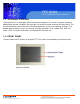
FPC 6104 10.4” Industrial Fanless Panel PC CHAPTER 1 INTRODUCTION 1.1 OVERVIEW The FPC6104 is an industrial flat panel PC. The FPC6104 can be used for machine control, production lines, kiosks and information stations. The FPC6104 is preinstalled with an Intel® Atom™ CPU for applications where more computing power is needed. The FPC6104 supports a second monitor for presenting information to customers or extending the display area.
FPC 6104 10.4” Industrial fanless Panel PC 1.1.1 FEATURES Some of the standard features of the FPC6104 flat panel PC include: Preinstalled 1.6 GHz Intel® Atom™ N270 CPU Preinstalled 1.0 GB DDR2 SO-DIMM memory module Aluminum die-casting IP 65, high brightness industrial panel SATA interface support Dual GbE support Simplified installation process Low power consumption and thermal distribution RoHS compliance 1.1.2 MODEL VARIATIONS 10.4” FPC6104 CPU: 1.6GHz INTEL ATOM N270 MEMORY: 1.
FPC 6104 10.4” Industrial Fanless Panel PC 1.2 EXTERNAL OVERVIEW The flat panel PC is a rectangular cubic structure that comprises of a screen, rear panel, top panel, bottom panel and two side panels (left and right). An aluminum frame surrounds the front screen. The rear panel provides screw holes for a wall-mounting bracket, and an arm mounting interface. The bottom panel provides access to external interface connectors that include LAN, USB 2.
FPC 6104 10.4” Industrial fanless Panel PC 1.2.2 REAR PANEL The rear panel provides access to a fan ventilation vent and four retention screw holes that support a wall-mounting bracket. Figure 1-3 shows the retention screw holes of the FPC6104. 1.2.3 BOTTOM PANEL The following is a list of the bottom panel peripheral device connectors on the 661 Brea Canyon Rd., Suite 3 Walnut, CA 91789 tel: 909.598.7388, fax: 909.598.0218 © Copyright 2011 Acnodes, Inc. All rights reserved.
FPC 6104 10.4” Industrial Fanless Panel PC 1.2.4 SIDE PANEL The both sides panel of the flat panel PC contain some vents for ventilation. 1.2.5 FRAME An aluminum frame surrounds the TFT LCD screen. The aluminum frames of the FPC6104 have small screw holes that are used when the flat panel PC is mounted into a rack or cabinet. These screws are circled in Figure 1-9. 661 Brea Canyon Rd., Suite 3 Walnut, CA 91789 tel: 909.598.7388, fax: 909.598.0218 © Copyright 2011 Acnodes, Inc. All rights reserved.
FPC 6104 10.4” Industrial fanless Panel PC 1.3 SPECIFICATIONS FPC6104- INTEL ATOM N270 PROCESSOR FRONT PANEL: Aluminum front panel CHASSIS: Heavy-duty steel LCD PANEL: 10.4” TFT LCD RESOLUTION: 800 x 600 (SVGA) BRIGHTNESS: 400 CD/M^2 BACKLIGHT MTBF: 50,000 hrs CONTRAST RATIO: 700:1 VIEWING ANGLE: 160/160 (H-V) TOUCH SCREEN: 5-wire resistive type with RS-232 interface CPU: 1.
FPC 6104 10.4” Industrial Fanless Panel PC DRIVE BAY: 1 x 2.5” HDD bay POWER: 60W power adapter MOUNTING: Stand, rack, wall, panel or arm COLOR: Silver OPERATING TEMPERATURE: -10~+50C with CF card, 0~+50C with HDD STORAGE TEMPERATURE: -20~+60C RELATIVE HUMIDITY: 5~95%, non-condensing VIBRATION: 5 - 17Hz, 0.1" double amplitude displacement. 17 - 640Hz, 1.5G acceleration, peak to peak. SHOCK:10G Acceleration, peak to peak (11ms) DIMENSION(MM): 311.5 x 242 x 77.8 NET/GROSS WEIGHT: 3.4 / 5.
FPC 6104 10.4” Industrial fanless Panel PC CHAPTER 2 DETAILED SPECIFICATIONS 2.1 DIMENSIONS 2.1.1 FPC6104 DIMENSIONS 661 Brea Canyon Rd., Suite 3 Walnut, CA 91789 tel: 909.598.7388, fax: 909.598.0218 © Copyright 2011 Acnodes, Inc. All rights reserved. Product description and product specifications are subject to change without notice. For latest product information, please visit Acnodes’ web site at www.acnodes.com.
FPC 6104 10.4” Industrial Fanless Panel PC 2.2 INTEL ATOM PROCESSOR A 45nm N270 Intel® Atom™ processor is installed in the system. The processor has a CPU speed of 1.6 GHz and a 533 MHz front side bus (FSB). The processor also comes with a 512 KB L2 cache and a 1.6 GHz L2 cache speed.
FPC 6104 10.4” Industrial fanless Panel PC 2.3.1.2 ADDITIONAL MEMORY The Intel® 945GSE is capable of supporting one 200-pin 2.0 GB (max.) 533 MHz or 400MHz DDR2 SDRAM SO-DIMM. If additional memory is required, please contact an IEIsales representative and discuss the necessary system requirement. 2.3.2 STORAGE CAPACITY The FPC6104 series supports an easily installed CompactFlash® Type II (CF Type II) memory disk. The FPC6104 also supports an internal 2.5" SATA drive.
FPC 6104 10.4” Industrial Fanless Panel PC 2.4 EXTERNAL PERIPHERAL INTERFACE CONNECTORS The following section describes the external peripheral interface connectors on the bottom panel of the subsystem. 2.4.1 SERIAL PORT CONNECTORS The FPC6104 has three serial ports. Two of these ports (COM1 and COM3) are RS-232 only port. The remaining serial port (COM2) can be configured as a RS-232, RS-422 or an RS-485 serial port. The FPC6104 has one extra RS-232 serial port on the bottom panel. 2.4.
FPC 6104 10.4” Industrial fanless Panel PC Integrated 10/100/1000 transceiver Supports PCI Express™ 1.1 Fully compliant with IEEE 802.3, IEEE 802.3u, IEEE 802.3ab Supports IEEE 802.1P Layer 2 Priority Encoding Supports IEEE 802.1Q VLAN tagging Serial EEPROM Transmit/Receive on-chip buffer support 64-pin QFN package (Green package) 2.4.3 EXTERNAL USB CONNECTORS There are two USB 2.0 connectors on the bottom panel of the FPC6120 . Both USB 2.
FPC 6104 10.4” Industrial Fanless Panel PC 2.5 FPC6104 FRONT SIDE 2.5.1 MONITOR A LCD screen is installed on the front of the FPC6104 series. The monitor maximum resolution is varied in different FPC6104 models. The screen is shown in Figure 2-11 below. 2.5.2 TOUCH-SCREEN MODULE A controller for the 4-wire/5-wire resistive touch screen is installed on the motherboard. The sensitive touch screen is accurate, reliable and durable. 2.6 GRAPHICS 2.6.
FPC 6104 10.4” Industrial fanless Panel PC 2.6.2 DUAL-DISPLAY The system supports dual display capabilities. The second display device can be connected to the FPC6104 through the VGA connector described above. 2.7 AUDIO The integrated AC'97 Audio compliant audio controller on the Intel® ICH7 Southbridge is connected to a 5.1 channel audio kit with RealTek ALC655 audio codec. The audio kit is then connected to three external audio jacks, which are then connected to compliant audio devices.
FPC 6104 10.4” Industrial Fanless Panel PC 2.8 SYSTEM POWER 2.8.1 FPC6104 POWER The standard system is shipped with a 90 V to 264 V AC power adapter that has a maximum power output of 60 W. The power adapter has a 12 V DC output connector. The FPC6104 series has one 12 V power input connector on the bottom panel. The power connector is shown in Figure 2-14 below. 661 Brea Canyon Rd., Suite 3 Walnut, CA 91789 tel: 909.598.7388, fax: 909.598.0218 © Copyright 2011 Acnodes, Inc. All rights reserved.
FPC 6104 10.4” Industrial fanless Panel PC CHAPTER 3 UNPACKING 3.1 UNPACKING To unpack the flat panel PC, follow the steps below: WARNING! The front side LCD screen has a protective plastic cover stuck to the screen. Only remove the plastic cover after the flat panel PC has been properly installed. This ensures the screen is protected during the installation process. Step 1: Use box cutters, a knife or a sharp pair of scissors that seals the top side of the external (second) box.
FPC 6104 10.4” Industrial Fanless Panel PC 3.1.1 PACKING LIST The FPC6104 flat panel PC is shipped with the following components: 1 x FPC6104 PANEL PC 1 x power adapter 1 x power cord 1 x KB/MS PS/2 Y-cable 1 x Mini jumper packe (2.0mm) 1 x Screw kit 1 x Panel mounting kit Optional 1 x Stand 1 x Rack mount Kit 1 x Arm 661 Brea Canyon Rd., Suite 3 Walnut, CA 91789 tel: 909.598.7388, fax: 909.598.0218 © Copyright 2011 Acnodes, Inc. All rights reserved.
FPC 6104 10.4” Industrial fanless Panel PC CHAPTER 4 INSTALLATION 4.1 ANTI-STATIC PRECAUTIONS WARNING: Failure to take ESD precautions during the maintenance of the FPC6104 may result in permanent damage to the FPC6104 and severe injury to the user. Electrostatic discharge (ESD) can cause serious damage to electronic components, including the FPC6104. Dry climates are especially susceptible to ESD.
FPC 6104 10.4” Industrial Fanless Panel PC 4.3 PREINSTALLED COMPONENTS The following components are all preinstalled. Motherboard TFT LCD screen 1.0 GB DDR2 memory module Resistive type touch screen Preinstalled customizations may include the following. Different DDR2 memory module Hard disk drive Component installation is described in the following sections. 4.4 PREINSTALLATION AND CONFIGURATION STEPS The following installation steps must be followed.
FPC 6104 10.4” Industrial fanless Panel PC 4.5 Remove the Back Cover 4.5.1 FPC6104 Back Cover Removal The back cover is secured to the chassis with nine retention screws, six on the rear panel and three on the top panel (Figure 4-3). Remove the nine retention screws and lift the cover off the FPC6104. .6 Jumper Settings he jumper settings are all described in Section 4.6. During normal installation, these ettings should not be changed .
FPC 6104 10.4” Industrial Fanless Panel PC Step 4: Insert the CF card. Gently insert the CF card into the socket making sure the socket pins are properly inserted into the socket. See Figure 4-4. 4.8 HDD Installation 4.8.1 FPD6104 HDD Installation To install the HDD into the FPC6104, please follow the steps below: Step 1: Remove the back cover. See Section 4.5.2 above. Step 2: Remove the HDD bracket from the FPC6104.
FPC 6104 10.4” Industrial fanless Panel PC Step 3: Attach the HDD bracket to the HDD. To do this, align the four retention screw holes in the HDD bracket with the retention screw holes on the bottom of the HDD. Insert four retention screws into the HDD bracket. (Figure 4-9). Step 4: Install the HDD into the FPC6104 by aligning the retention screw holes in the HDD bracket with the retention screw holes on the panel PC. Insert the four retention screws.
FPC 6104 10.4” Industrial Fanless Panel PC 4.10 Jumper Settings NOTE: A jumper is a metal bridge used to close an electrical circuit. It consists of two or three metal pins and a small metal clip (often protected by a plastic cover) that slides over the pins to connect them. To CLOSE/SHORT a jumper means connecting the pins of the jumper with the plastic clip and to OPEN a jumper means removing the plastic clip from a jumper. The following jumpers can be found on the motherboard installed in the FPC6104.
FPC 6104 10.4” Industrial fanless Panel PC 4.10.1 ACCESS THE JUMPERS To access the jumpers, remove the back panel. To remove the back panel, please refer to Section 4.5. 4.10.2 Preconfigured Jumpers WARNING: Do not change the settings on the jumpers in described here. Doing so may disable or damage the system. The following jumpers are preconfigured for the FPC6104. Users should no change these jumpers (Table 4-2). 4.10.
FPC 6104 10.4” Industrial Fanless Panel PC 4.9.4 CF Card Setup Jumper Label: JCF1 Jumper Type: 2-pin header Jumper Settings:See Table 4-4 Jumper Location: See Figure 4-17 The CF Card Setup jumper sets the CF Type I card or CF Type II cards as either the slave device or the master device. CF Card Setup jumper settings are shown in Table 4-4. The CF Card Setup jumper location is shown in Figure 4-17. 661 Brea Canyon Rd., Suite 3 Walnut, CA 91789 tel: 909.598.7388, fax: 909.598.
FPC 6104 10.4” Industrial fanless Panel PC 4.9.5 Clear CMOS Jumper Jumper Jumper Jumper Jumper Label: J_CMOS1 Type: 3-pin header Settings:See Table 4-5 Location: See Figure 4-18 If the FPC6104 fails to boot due to improper BIOS settings, the clear CMOS jumper clears the CMOS data and resets the system BIOS information. To do this, use the jumper cap to close pins 2 and 3 for a few seconds then reinstall the jumper clip back to pins 1 and 2.
FPC 6104 10.4” Industrial Fanless Panel PC The location of the clear CMOS jumper is shown in Figure 4-18 below. 4.9.6 COM 2 Function Select Jumper Jumper Jumper Jumper Jumper Label: JP1 Type: 6-pin header Settings:See Table 4-6 Location: See Figure 4-19 The COM 2 Function Select jumper sets the communication protocol used by the second serial communications port (COM 2) as RS-232, RS-422 or RS-485. The COM 2 Function Select settings are shown in Table 4-6. 661 Brea Canyon Rd.
FPC 6104 10.4” Industrial fanless Panel PC The COM 2 Function Select jumper location is shown in Figure 4-19. 4.9.6.1 COM2 RS-422 and RS-485 Pinouts The pinouts for RS-422 and RS-485 operation of external serial port COM 2 are detailed below. 661 Brea Canyon Rd., Suite 3 Walnut, CA 91789 tel: 909.598.7388, fax: 909.598.0218 © Copyright 2011 Acnodes, Inc. All rights reserved. Product description and product specifications are subject to change without notice.
FPC 6104 10.4” Industrial Fanless Panel PC 4.10Mounting the System WARNING! When mounting the flat panel PC onto an arm, onto the wall or onto a panel, it is better to have more than one person to help with the installation to make sure the flat panel PC does not fall down and get damaged. The four methods of mounting the flat panel PC are listed below. Wall mounting Panel mounting Arm mounting Rack mounting The four mounting methods are described below. 4.10.
FPC 6104 10.4” Industrial fanless Panel PC Step 1: Align the mounting screws on the monitor rear panel with the mounting holes on the bracket. Step 2: Carefully insert the screws through the holes and gently pull the monitor downwards until the monitor rests securely in the slotted holes (Figure 4-21). Ensure that all four of the mounting screws fit snuggly into their respective slotted holes. NOTE: In the diagram below the bracket is already installed on the wall.
FPC 6104 10.4” Industrial Fanless Panel PC 661 Brea Canyon Rd., Suite 3 Walnut, CA 91789 tel: 909.598.7388, fax: 909.598.0218 © Copyright 2011 Acnodes, Inc. All rights reserved. Product description and product specifications are subject to change without notice. For latest product information, please visit Acnodes’ web site at www.acnodes.com.
FPC 6104 10.4” Industrial fanless Panel PC 4.10.2 Panel Mounting 4.10.2.1 FPC6104 To mount the FPC6104 flat panel PC into a panel, please follow the steps below. Step 1: Select the position in the panel to mount the panel PC. Step 2: Cut out a section from the panel that corresponds to the dimensions of the flat panel PC chassis. The panel section that is cut out must be smaller than the size of the aluminum frame that surrounds the TFT LCD panel but just large enough for the chassis to fit through.
FPC 6104 10.4” Industrial Fanless Panel PC 4.10.3 Arm Mounting The flat panel PC is VESA (Video Electronics Standards Association) compliant and can be mounted on an arm with a 100 mm interface pad. To mount the flat panel PC on an arm, please follow the steps below. Step 1: The arm is a separately purchased item. Please correctly mount the arm onto the surface it uses as a base. To do this, refer to the installation documentation that came with the mounting arm.
FPC 6104 10.4” Industrial fanless Panel PC Step 4: Secure the flat panel PC to the interface pad by inserting four retention screws through the bottom of the mounting arm interface pad and into the flat panel PC. 4.10.4 Cabinet and Rack Installation The FPC6104 flat panel PC can be installed into a cabinet or rack. To do this, please follow the steps below. 4.10.4.
FPC 6104 10.4” Industrial Fanless Panel PC Step 4: Secure the rack/cabinet bracket to the FPC6104 flat panel PC by inserting the retention screws (Figure 4-33). Step 5: Follow Step 4 and Step 5 of the FPC6104 Cabinet and Rack Installation procedures to complete the whole installation process. 4.11 Rear Panel Connectors 4.11.1 Keyboard and Mouse Connection Two PS/2 connectors on the bottom panel facilitate the connection of a mouse and a keyboard.
FPC 6104 10.4” Industrial fanless Panel PC Step 1: Locate the RJ-45 connectors on the bottom panel of the FPC6104. Step 2: Align the connectors. Align the RJ-45 connector on the LAN cable with one of the RJ-45 connectors on the bottom panel of the FPC6104. See Figure 4-34. Step 3: Insert the LAN cable RJ-45 connector. Once aligned, gently insert the LAN cable RJ-45 connector into the onboard RJ-45 connector. 4.11.
FPC 6104 10.4” Industrial Fanless Panel PC Step 3: Secure the connector. Secure the serial device connector to the external interface by tightening the two retention screws on either side of the connector. 4.11.4 USB Device Connection To connect a USB 2.0 or USB 1.1 device, please follow the instructions below. Step 1: Locate the USB connectors. The locations of the USB connectors are shown in Chapter 2. Step 2: Align the connectors.
FPC 6104 10.4” Industrial fanless Panel PC Step 3: Insert the device connector. Once aligned, gently insert the USB device connector into the onboard connector. 4.11.5 VGA Monitor Connection The FPC6104 has a single female DB-15 connector on the external peripheral interface panel. The DB-15 connector is connected to a CRT or VGA monitor. To connect a monitor to the FPC6104, please follow the instructions below. Step 1: Locate the female DB-15 connector.
FPC 6104 10.4” Industrial Fanless Panel PC Step 4: Secure the connector. Secure the DB-15 VGA connector from the VGA monitor to the external interface by tightening the two retention screws on either side of the connector. 4.12 System Maintenance If the components of the flat panel PC fail, they must be replaced. Please contact the system reseller or vendor to purchase the replacement parts. Replacement instructions for the above listed components are described below.
FPC 6104 10.4” Industrial fanless Panel PC CHAPTER 5 BIOS SCREENS 5.1 Introduction A licensed copy of AMI BIOS is preprogrammed into the ROM BIOS. The BIOS setup program allows users to modify the basic system configuration. This chapter describes how to access the BIOS setup program and the configuration options that may be changed. 5.1.1 Starting Setup The AMI BIOS is activated when the computer is turned on. The setup program can be activated in one of two ways. 1.
FPC 6104 10.4” Industrial Fanless Panel PC 5.1.3 Getting Help When F1 is pressed a small help window describing the appropriate keys to use and the possible selections for the highlighted item appears. To exit the Help Window press ESC or the F1 key again. 5.1.4 Unable to Reboot After Configuration Changes If the computer cannot boot after changes to the system configuration is made, CMOS defaults. Use the jumper described in Chapter 5. 5.1.
FPC 6104 10.4” Industrial fanless Panel PC 5.2 Main The Main BIOS menu (BIOS Menu 1) appears when the BIOS Setup program is entered. The Main menu gives an overview of the basic system information. System Overview The System Overview lists a brief summary of different system components. The fields in System Overview cannot be changed.
FPC 6104 10.4” Industrial Fanless Panel PC -System Memory: Displays the auto-detected system memory. o Size: Lists memory size The System Overview field also has two user configurable fields: System Time [xx:xx:xx] Use the System Time option to set the system time. Manually enter the hours, minutes and seconds. System Date [xx/xx/xx] Use the System Date option to set the system date. Manually enter the day, month and year. 5.
FPC 6104 10.4” Industrial fanless Panel PC 5.3.1 CPU Configuration Use the CPU Configuration menu (BIOS Menu 3) to view detailed CPU specifications and configure the CPU. 661 Brea Canyon Rd., Suite 3 Walnut, CA 91789 tel: 909.598.7388, fax: 909.598.0218 © Copyright 2011 Acnodes, Inc. All rights reserved. Product description and product specifications are subject to change without notice. For latest product information, please visit Acnodes’ web site at www.acnodes.com.
FPC 6104 10.4” Industrial Fanless Panel PC The CPU Configuration menu (BIOS Menu 3) lists the following CPU details: Manufacturer: Lists the name of the CPU manufacturer Brand String: Lists the brand name of the CPU being used Frequency: Lists the CPU processing speed FSB Speed: Lists the FSB speed Cache L1: Lists the CPU L1 cache size Cache L2: Lists the CPU L2 cache size 5.3.
FPC 6104 10.4” Industrial fanless Panel PC ATA/IDE Configurations [Compatible] Use the ATA/IDE Configurations option to configure the ATA/IDE controller. Disabled Compatible Disables the on-board ATA/IDE controller. Configures the on-board ATA/IDE controller to be in compatible mode. In this mode, a SATA channel will replace one of the IDE channels. This mode sup ports up to 4 storage devices. Enhanced (DEFAULT) Configures the on-board ATA/IDE controller to be in Enhanced mode.
FPC 6104 10.4” Industrial Fanless Panel PC IDE Master and IDE Slave When entering setup, BIOS auto detects the presence of IDE devices. BIOS displays the status of the auto detected IDE devices. The following IDE devices are detected and are shown in the IDE Configuration menu: Primary IDE Master Primary IDE Slave Secondary IDE Master Secondary IDE Slave The IDE Configuration menu (BIOS Menu 4) allows changes to the configurations for the IDE devices installed in the system.
FPC 6104 10.4” Industrial fanless Panel PC Auto-Detected Drive Parameters The "grayed-out" items in the left frame are IDE disk drive parameters automatically detected from the firmware of the selected IDE disk drive. The drive parameters are listed as follows: Device: Lists the device type (e.g. hard disk, CD-ROM etc.) Type: Indicates the type of devices a user can manually select Vendor: Lists the device manufacturer Size: List the storage capacity of the device.
FPC 6104 10.4” Industrial Fanless Panel PC Use the LBA/Large Mode option to disable or enable BIOS to auto detects LBA (Logical Block Addressing). LBA is a method of addressing data on a disk drive. In LBA mode, the maximum drive capacity is 137 GB. Disabled BIOS is prevented from using the LBA mode control on the specified channel. Auto DEFAULT BIOS auto detects the LBA mode control on the specified channel.
FPC 6104 10.4” Industrial fanless Panel PC DMA Mode [Auto] Use the DMA Mode BIOS selection to adjust the DMA mode options. Auto DEFAULT BIOS auto detects the DMA mode. Use this value if the IDE disk drive support cannot be determined. SWDMA0 Single Word DMA mode 0 selected with a maximum data transfer rate of 2.1MBps SWDMA1 Single Word DMA mode 1 selected with a maximum data transfer rate of 4.2MBps SWDMA2 Single Word DMA mode 2 selected with a maximum data transfer rate of 8.
FPC 6104 10.4” Industrial Fanless Panel PC UDMA3 Ultra DMA mode 3 selected with a maximum data transfer rate of 44MBps (To use this mode, it is required that an 80-conductor ATA cable is used.) UDMA4 Ultra DMA mode 4 selected with a maximum data transfer rate of 66.6MBps (To use this mode, it is required that an 80-conductor ATA cable is used.) UDMA5 Ultra DMA mode 5 selected with a maximum data transfer rate of 99.9MBps (To use this mode, it is required that an 80-conductor ATA cable is used.) S.M.A.R.
FPC 6104 10.4” Industrial fanless Panel PC 5.3.3 Super IO Configuration Use the Super IO Configuration menu (BIOS Menu 6) to set or change the configurations for the FDD controllers, parallel ports and serial ports. Parallel Port Address [Disabled] Use the Parallel Port Address option to select the parallel port base address.
FPC 6104 10.4” Industrial Fanless Panel PC Normal DEFAULT The normal parallel port mode is the standard mode for parallel port operation. EPP The parallel port operates in the enhanced parallel port mode(EPP). The EPP mode supports bi-directional communication between the system and the parallel port device and the transmission rates between the two are much faster than the Normal mode. ECP+EPP The parallel port operates in the extended capabilities port (ECP) mode.
FPC 6104 10.4” Industrial fanless Panel PC Normal IrDA ASK IR DEFAULT Serial Port 1 mode is normal Serial Port 1 mode is IrDA Serial Port 1 mode is ASK IR Serial Port2 Address [2F8/IRQ3] Use the Serial Port2 Address option to select the Serial Port 2 base address.
FPC 6104 10.4” Industrial Fanless Panel PC Serial Port4 Address [2E8] Use the Serial Port4 IRQ option to select the interrupt address for serial port 4. Disabled No base address is assigned to serial port 3 3E8 Serial port 4 I/O port address is 3E8 2E8 DEFAULT Serial port 4 I/O port address is 2E8 2F0 Serial port 4 I/O port address is 2F0 2E0 Serial port 4 I/O port address is 2E0 Serial Port4 IRQ [10] Use the Serial Port4 IRQ option to select the interrupt address for serial port 4.
FPC 6104 10.4” Industrial fanless Panel PC Full On Mode DEFAULT Fan is on all the time Automatic mode Fan is off when the temperature is low enough. Parameters must be set by the user. PWM Manual mode Pulse width modulation set manually When the CPU FAN Mode Setting option is in the Automatic Mode, the following parameters can be set. CPU Temp. Limit of OFF CPU Temp.
FPC 6104 10.4” Industrial Fanless Panel PC Minimum Value: 0°C Maximum Value: 127°C CPU Fan Start PWM [070] The Fan 3 Start PWM option can only be set if the CPU FAN Mode Setting option is set to Automatic Mode. Use the Fan 3 Start PWM option to select the PWM mode the fan starts to rotate with after the temperature specified in the Temperature 3 Limit of Start is exceeded. The Super I/O chipset supports 128 PWM modes.
FPC 6104 10.4” Industrial fanless Panel PC 5.3.5 Power Configuration The Power Configuration menu (BIOS Menu 8) configures the Advanced Configuration and Power Interface (ACPI) and Power Management (APM) options. 661 Brea Canyon Rd., Suite 3 Walnut, CA 91789 tel: 909.598.7388, fax: 909.598.0218 © Copyright 2011 Acnodes, Inc. All rights reserved. Product description and product specifications are subject to change without notice. For latest product information, please visit Acnodes’ web site at www.
FPC 6104 10.4” Industrial Fanless Panel PC 5.3.5.1 ACPI configuration The ACPI Configuration menu (BIOS Menu 9) configures the Advanced Configuration and Power Interface (ACPI). Suspend Mode [S1(POS)] Use the Suspend Mode BIOS option to specify the sleep state the system enters when it is not being used. S1 (POS) DEFAULT System appears off. The CPU is stopped; RAM is refreshed; the system is running in a low power mode. S3 (STR) System appears off.
FPC 6104 10.4” Industrial fanless Panel PC 5.3.5.2 APM Configuration The APM Configuration menu (BIOS Menu 10) allows the advanced power management options to be configured. Restore on AC Power Loss [Last State] Use the Restore on AC Power Loss BIOS option to specify what state the system returns to if there is a sudden loss of power to the system. Power Off The system remains turned off Power On The system turns on Last State DEFAULT The system returns to its previous state.
FPC 6104 10.4” Industrial Fanless Panel PC Resume on Keyboard/Mouse [Disabled] Use the Resume on Keyboard/Mouse BIOS option to enable activity on either the keyboard or mouse to rouse the system from a suspend or standby state. That is, the system is roused when the mouse is moved or a button on the keyboard is pressed.
FPC 6104 10.4” Industrial fanless Panel PC Remote Access [Disabled] Use the Remote Access option to enable or disable access to the remote functionalities of the system. Disabled DEFAULT Remote access is disabled. Enabled Remote access configuration options shown below appear: -Serial Port Number -Serial Port Mode -Flow Control -Redirection after BIOS POST -Terminal Type -VT-UTF8 Combo Key Support These configuration options are discussed below.
FPC 6104 10.4” Industrial Fanless Panel PC Base Address, IRQ [2F8h,3] The Base Address, IRQ option cannot be configured and only shows the interrupt address of the serial port listed above. Serial Port Mode [115200 8,n,1] Use the Serial Port Mode option to select baud rate through which the console redirection is made.
FPC 6104 10.4” Industrial fanless Panel PC on the standard PC 101-key layout, however. The VT-UTF8 convention makes available additional keys that are not provided by VT100 for the PC 101 keyboard. Disabled DEFAULT Disables the VT-UTF8 terminal keys Enabled Enables the VT-UTF8 combination key. Support for ANSI/VT100 terminals Sredir Memory Display Delay [Disabled] Use the Sredir Memory Display Delay option to select the delay before memory information is displayed.
FPC 6104 10.4” Industrial Fanless Panel PC USB Functions [Enabled] Use the USB Function option to enable or disable the USB controllers. Disabled USB controllers are enabled Enabled DEFAULT USB controllers are disabled USB 2.0 Controller [Enabled] The USB 2.0 Controller BIOS option enables or disables the USB 2.0 controller Disabled USB function disabled Enabled DEFAULT USB function enabled USB2.0 Controller Mode [HiSpeed] The USB2.0 Controller Mode BIOS option sets the speed of the USB2.0 controller.
FPC 6104 10.4” Industrial fanless Panel PC 5.4 PCI/PnP Use the PCI/PnP menu (BIOS Menu 13) to configure advanced PCI and PnP settings. WARNING: Setting wrong values for the BIOS selections in the PCIPnP BIOS menu may cause the system to malfunction. IRQ# [Available] Use the IRQ# address to specify what IRQs can be assigned to a particular peripheral device.
FPC 6104 10.4” Industrial Fanless Panel PC DMA Channel# [Available] Use the DMA Channel# option to assign a specific DMA channel to a particular PCI/PnP device.
FPC 6104 10.4” Industrial fanless Panel PC 5.5.1 Boot Settings Configuration Use the Boot Settings Configuration menu (BIOS Menu 14) to configure advanced system boot options. Quick Boot [Enabled] Use the Quick Boot BIOS option to make the computer speed up the boot process. Disabled No POST procedures are skipped Enabled DEFAULT Some POST procedures are skipped to decrease the system boot time Quiet Boot [Disabled] Use the Quiet Boot BIOS option to select the screen display when the system boots.
FPC 6104 10.4” Industrial Fanless Panel PC Force BIOS DEFAULT Allows the computer system to force a third party BIOS to display during system boot. Keep Current Allows the computer system to display the information during system boot. Bootup Num-Lock [Off] The Bootup Num-Lock BIOS option allows the Number Lock setting to be modified during boot up. Off DEFAULT Does not enable the keyboard Number Lock automatically.
FPC 6104 10.4” Industrial fanless Panel PC 661 Brea Canyon Rd., Suite 3 Walnut, CA 91789 tel: 909.598.7388, fax: 909.598.0218 © Copyright 2011 Acnodes, Inc. All rights reserved. Product description and product specifications are subject to change without notice. For latest product information, please visit Acnodes’ web site at www.acnodes.com.
FPC 6104 10.4” Industrial Fanless Panel PC 5.6 Security Use the Security menu (BIOS Menu 17) to set system and user passwords. Change Supervisor Password Use the Change Supervisor Password to set or change a supervisor password. The default for this option is Not Installed. If a supervisor password must be installed, select this field and enter the password. After the password has been added, Install appears next to Change Supervisor Password.
FPC 6104 10.4” Industrial fanless Panel PC 5.7 Chipset Use the Chipset menu (BIOS Menu 18) to access the NorthBridge and SouthBridge configuration menus WARNING! Setting the wrong values for the Chipset BIOS selections in the Chipset BIOS menu may cause the system to malfunction. 661 Brea Canyon Rd., Suite 3 Walnut, CA 91789 tel: 909.598.7388, fax: 909.598.0218 © Copyright 2011 Acnodes, Inc. All rights reserved. Product description and product specifications are subject to change without notice.
FPC 6104 10.4” Industrial Fanless Panel PC 5.7.1 North Bridge Chipset Configuration Use the North Bridge Chipset Configuration menu (BIOS Menu 18) to configure the Northbridge chipset settings. Memory Hole [Disabled] The Memory Hole reserves the memory space between 15MB and 16MB for ISA expansion cards that require a specified area of memory to work properly. If an older ISA expansion card is used, please refer to the documentation that came with the card to see if it is necessary to reserve the space.
FPC 6104 10.4” Industrial fanless Panel PC DVMT Mode Select [DVMT Mode] Use the DVMT Mode Select option to select the Intel Dynamic Video Memory Technology (DVMT) operating mode. Fixed Mode A fixed portion of graphics memory is reserved as graphics memory. DVMT Mode DEFAULT Graphics memory is dynamically allocated according to the system and graphics needs. Combo Mode A fixed portion of graphics memory is reserved as graphics memory.
FPC 6104 10.4” Industrial Fanless Panel PC LCD Brightness Control Use the LCD Brightness Control option to specify the brightness of the LCD panel as a percentage. Default setting is 100% TV Standard The TV Standard option specifies the TV type connected to the system. VBIOS-Default DEFAULT NTSC PAL SECAM SMPTE240M ITU-R television SMPTE260M SMPTE295M SMPTE296M EIA-770.2 EIA-770.
FPC 6104 10.4” Industrial fanless Panel PC Audio Controller [All Disabled] The Audio Controller option enables or disables the audio controller. Azalia Audio controller configured as Azalia AC'97 Audio Only The on-board AC'97 audio controller is enabled. All Disabled DEFAULT The on-board audio controller is disabled. 5.8 Exit Use the Exit menu (BIOS Menu 21) to load default BIOS values, optimal failsafe values and to save configuration changes.
FPC 6104 10.4” Industrial Fanless Panel PC Discard Changes and Exit Use the Discard Changes and Exit option to exit the BIOS configuration setup program without saving the changes made to the system. Discard Changes Use the Discard Changes option to discard the changes and remain in the BIOS configuration setup program. Load Optimal Defaults Use the Load Optimal Defaults option to load the optimal default values for each of the parameters on the Setup menus. F9 key can be used for this operation.
FPC 6104 10.4” Industrial fanless Panel PC CHAPTER 6 DRIVER INSTALLATION 6.1 Available Software Drivers NOTE: The content of the CD may vary throughout the life cycle of the product and is subject to change without prior notice. You may visit the IEI website or contact technical support for the latest updates. The following drivers can be installed on the system. Chipset driver VGA driver LAN driver Installation instructions are given below. 6.
FPC 6104 10.4” Industrial Fanless Panel PC 6.3 Chipset Driver Installation To install the chipset driver, please follow the steps below: Step 1: Select the INF driver from the list in Figure 6-1. Step 2: A new window opens (Figure 6-2). 661 Brea Canyon Rd., Suite 3 Walnut, CA 91789 tel: 909.598.7388, fax: 909.598.0218 © Copyright 2011 Acnodes, Inc. All rights reserved. Product description and product specifications are subject to change without notice.
FPC 6104 10.4” Industrial fanless Panel PC Step 3: Double click the infinst_Autol icon in Figure 6-2. Step 4: The welcome screen in Figure 6-3 appears. Step 5: Click NEXT in Figure 6-3 to continue the installation process. Step 6: The license agreement in Figure 6-4 appears. Step 7: Click YES to continue the setup. Step 8: The Readme file in Figure 6-5 appears. 661 Brea Canyon Rd., Suite 3 Walnut, CA 91789 tel: 909.598.7388, fax: 909.598.0218 © Copyright 2011 Acnodes, Inc. All rights reserved.
FPC 6104 10.4” Industrial Fanless Panel PC Step 9: Click NEXT in Figure 6-5 to start the driver installation. Step 10: After the driver installation process is complete, a confirmation screen (Figure 6-6) appears. 6.4 Intel® Graphics Media Accelerator Driver To install the chipset driver, please follow the steps below: Step 1: Select the VGA driver from the list in Figure 6-1. 661 Brea Canyon Rd., Suite 3 Walnut, CA 91789 tel: 909.598.7388, fax: 909.598.0218 © Copyright 2011 Acnodes, Inc.
FPC 6104 10.4” Industrial fanless Panel PC Step 2: A new window opens (Figure 6-7). Step 3: Select the operating system from those shown in Figure 6-7. Step 4: A new window appears (Figure 6-8). Step 5: Click the installation program icon in Figure 6-8. 661 Brea Canyon Rd., Suite 3 Walnut, CA 91789 tel: 909.598.7388, fax: 909.598.0218 © Copyright 2011 Acnodes, Inc. All rights reserved. Product description and product specifications are subject to change without notice.
FPC 6104 10.4” Industrial Fanless Panel PC Step 6: The Readme information file shown in Figure 6-9 appears. Step 7: Click NEXT to extract the GMA driver files. See Figure 6-10. Step 8: The welcome screen shown in Figure 6-11 appears. 661 Brea Canyon Rd., Suite 3 Walnut, CA 91789 tel: 909.598.7388, fax: 909.598.0218 © Copyright 2011 Acnodes, Inc. All rights reserved. Product description and product specifications are subject to change without notice.
FPC 6104 10.4” Industrial fanless Panel PC Step 9: To continue the installation process, click NEXT. Step 10: The license agreement in Figure 6-12 appears. Step 11: Click the YES in Figure 6-12 to continue. Step 12: The installation notice shown in Figure 6-13 appears. 661 Brea Canyon Rd., Suite 3 Walnut, CA 91789 tel: 909.598.7388, fax: 909.598.0218 © Copyright 2011 Acnodes, Inc. All rights reserved. Product description and product specifications are subject to change without notice.
FPC 6104 10.4” Industrial Fanless Panel PC Step 13: A confirmation screen shown in Figure 6-14 appears. Step 14: After selecting when to restart the computer in Figure 6-14, click FINISH. 6.5 Broadcom LAN Driver (for GbE LAN) Installation To install the Broadcom LAN driver, please follow the steps below. Step 1: Open Windows Control Panel (Figure 6-15). 661 Brea Canyon Rd., Suite 3 Walnut, CA 91789 tel: 909.598.7388, fax: 909.598.0218 © Copyright 2011 Acnodes, Inc. All rights reserved.
FPC 6104 10.4” Industrial fanless Panel PC Step 2: Double click the System icon (Figure 6-16). Step 3: Double click the Device Manager tab (Figure 6-17). 661 Brea Canyon Rd., Suite 3 Walnut, CA 91789 tel: 909.598.7388, fax: 909.598.0218 © Copyright 2011 Acnodes, Inc. All rights reserved. Product description and product specifications are subject to change without notice. For latest product information, please visit Acnodes’ web site at www.acnodes.com.
FPC 6104 10.4” Industrial Fanless Panel PC Step 4: A list of system hardware devices appears (Figure 6-18). Step 5: Double click the listed device that has question marks next to it. (This means Windows does not recognize the device). Step 6: The Device Driver Wizard appears (Figure 6-19). Click NEXT to continue. 661 Brea Canyon Rd., Suite 3 Walnut, CA 91789 tel: 909.598.7388, fax: 909.598.0218 © Copyright 2011 Acnodes, Inc. All rights reserved.
FPC 6104 10.4” Industrial fanless Panel PC Step 7: Select "Specify a Location" in the Locate Driver Files window (Figure 6-20). Click NEXT to continue. Step 8: Select the proper OS folder under the "X:\3-LAN\BROADCOM BCM57xx Drivers" directory (Figure 6-21) in the location browsing window, where "X:\" is the system CD drive. 661 Brea Canyon Rd., Suite 3 Walnut, CA 91789 tel: 909.598.7388, fax: 909.598.0218 © Copyright 2011 Acnodes, Inc. All rights reserved.
FPC 6104 10.4” Industrial Fanless Panel PC Step 9: Click OK to continue. A driver files location menu window appears. Click NEXT to continue. The driver is installed. 6.6 Realtek AC`97 Audio Driver (ALC665) Installation To install the Realtek AC `97 audio driver, please follow the steps below. 6.6.1 BIOS Setup Step 1: Enter the BIOS setup. To do this, reboot the system and press DEL during POST. Step 2: Go to the Southbridge Configuration menu. Set the Audio Controller option to [AC`97]. See Section 5.7.
FPC 6104 10.4” Industrial fanless Panel PC Step 3: Double-click the Setup.exe file to begin the driver installation process. Step 4: Once you double click the Setup icon, the install shield wizard for the audio driver starts. See Figure 6-23. Step 5: The Realtek Audio Setup prepares the install shield to guide you through the rest of the setup process. See Figure 6-24. 661 Brea Canyon Rd., Suite 3 Walnut, CA 91789 tel: 909.598.7388, fax: 909.598.0218 © Copyright 2011 Acnodes, Inc. All rights reserved.
FPC 6104 10.4” Industrial Fanless Panel PC Step 6: After the install shield is prepared, the welcome screen shown in Figure 6-25 appears. To continue the installation process, click the "NEXT" button. The install shield starts to configure the new software as shown in Figure 6-25. Step 7: At this stage the "Digital Signal Not Found" screen appears (Figure 6-26). To continue the installation process, click the "YES" button. 661 Brea Canyon Rd., Suite 3 Walnut, CA 91789 tel: 909.598.7388, fax: 909.598.
FPC 6104 10.4” Industrial fanless Panel PC Step 8: After clicking the "YES" button in Figure 6-26, the installation of the driver begins (Figure 627). Step 9: After the driver installation process is complete, a confirmation screen shown in Figure 6-28 appears. 661 Brea Canyon Rd., Suite 3 Walnut, CA 91789 tel: 909.598.7388, fax: 909.598.0218 © Copyright 2011 Acnodes, Inc. All rights reserved. Product description and product specifications are subject to change without notice.
FPC 6104 10.4” Industrial Fanless Panel PC Step 10: The confirmation screen shown in Figure 6-28 allows you to restart the computer immediately after the installation is complete or to restart the computer later. For the settings to take effect the computer must be restarted. Once you have decided when to restart the computer, click the "FINISH" button. 661 Brea Canyon Rd., Suite 3 Walnut, CA 91789 tel: 909.598.7388, fax: 909.598.0218 © Copyright 2011 Acnodes, Inc. All rights reserved.
FPC 6104 10.4” Industrial fanless Panel PC A. SAFETY PRECAUTIONS WARNING: The precautions outlined in this chapter should be strictly followed. Failure to follow these precautions may result in permanent damage to the FPC6104. A.1 Safety Precautions Please follow the safety precautions outlined in the sections that follow: A.1.1 General Safety Precautions Please ensure the following safety precautions are adhered to at all times.
FPC 6104 10.4” Industrial Fanless Panel PC A.1.2 Anti-static Precautions WARNING: Failure to take ESD precautions during the installation of the FPC6104 permanent damage to the FPC6104 and severe injury to the user. may result in Electrostatic discharge (ESD) can cause serious damage to electronic components, including the FPC6104. Dry climates are especially susceptible to ESD.
FPC 6104 10.4” Industrial fanless Panel PC A.1.3 Product Disposal CAUTION: Risk of explosion if battery is replaced by and incorrect type. Only certified engineers should replace the on-board battery. Dispose of used batteries according to instructions and local regulations. -Outside the European Union - If you wish to dispose of used electrical and electronic products outside the European Union, please contact your local authority so as to comply with the correct disposal method.
FPC 6104 10.4” Industrial Fanless Panel PC -Turn the FPC6104 off before cleaning the FPC6104. -Never drop any objects or liquids through the openings of the FPC6104. -Be cautious of any possible allergic reactions to solvents or chemicals used when cleaning the FPC6104. -Avoid eating, drinking and smoking within vicinity of the FPC6104. A.2.2 Cleaning Tools Some components in the FPC6104 may only be cleaned using a product specifically designed for the purpose.
FPC 6104 10.4” Industrial fanless Panel PC B. BIOS CONFIGURATION OPTIONS ? ? ? ? ? ? ? ? ? ? ? ? ? ? ? ? ? ? ? ? ? ? ? ? ? ? ? ? ? ? ? ? ? System Overview .................................................................................................................66 System Time [xx:xx:xx] .........................................................................................................67 System Date [xx/xx/xx] .....................................................................................
FPC 6104 10.4” Industrial Fanless Panel PC ? ? ? ? ? ? ? ? ? ? ? ? ? ? ? ? ? ? ? ? ? ? ? ? ? ? ? ? ? ? ? ? ? ? ? Restore on AC Power Loss [Last State] ............................................................................86 Power Button Mode [On/Off]...............................................................................................86 Resume on Keyboard/Mouse [Disabled] ...........................................................................87 Resume on Ring [Disabled] ................
FPC 6104 10.4” Industrial fanless Panel PC ? ? ? ? ? ? ? ? ? ? ? ? ? ? ? Change Supervisor Password ......................................................................................... 101 Change User Password .................................................................................................... 101 Memory Hole [Disabled] ................................................................................................... 103 Internal Graphics Mode Select [Enable, 8MB] ...................
FPC 6104 10.4” Industrial Fanless Panel PC C. WATCHDOG TIMER NOTE: The following discussion applies to DOS environment. IEI support is contacted or the IEI website visited for specific drivers for more sophisticated operating systems, e.g., Windows and Linux. The Watchdog Timer is provided to ensure that standalone systems can always recover from catastrophic conditions that cause the CPU to crash. This condition may have occurred by external EMIs or a software bug.
FPC 6104 10.4” Industrial fanless Panel PC NOTE: When exiting a program it is necessary to disable the Watchdog Timer, otherwise the system resets.
FPC 6104 10.4” Industrial Fanless Panel PC D. HAZARDOUS MATERIALS DISCLOSURE D.1 Hazardous Materials Disclosure Table for IPB Products Certified as RoHS Compliant Under 2002/95/EC Without Mercury The details provided in this appendix are to ensure that the product is compliant with the Peoples Republic of China (China) RoHS standards. The table below acknowledges the presences of small quantities of certain materials in the product, and is applicable to China RoHS only.
FPC 6104 10.4” Industrial fanless Panel PC 661 Brea Canyon Rd., Suite 3 Walnut, CA 91789 tel: 909.598.7388, fax: 909.598.0218 © Copyright 2011 Acnodes, Inc. All rights reserved. Product description and product specifications are subject to change without notice. For latest product information, please visit Acnodes’ web site at www.acnodes.com.
FPC 6104 10.4” Industrial Fanless Panel PC 661 Brea Canyon Rd., Suite 3 Walnut, CA 91789 tel: 909.598.7388, fax: 909.598.0218 © Copyright 2011 Acnodes, Inc. All rights reserved. Product description and product specifications are subject to change without notice. For latest product information, please visit Acnodes’ web site at www.acnodes.com.