
User`s manual


16
KOOLMASTER PP20-VS2 rev.00
KOOLMASTER PP20-VS2
4.8.4. Night Settings
Night functions allow changing the target
room temperature and the minimum ventila-
tion level when the night comes (refer to the
Minimum Ventilation chapter of this manual
to set the night fan speed).
Select:1.
Current Conditions (Main Menu)
Setup *
User
Day/Night
* A password may be required to access this menu.
Day Night Settings
Night SetPoint? Yes
Night Min.Vent? Yes
Night Heater Offset Yes
Day Time 6:00A h:m
NightTime 6:00P h:m
Transition 60 min
Set the following parameters:2.
Night Set Point? — Select “Yes” to use a
different target temperature at night; select
“No” to disable this function.
Nig ht M ini m u m Ve nt i l at i on? — The controller
can use a different minimum ventilation fan
speed at night. Select “Yes” to use particular
minimum ventilation night settings.
Nig ht Hea te r Offs et — The controller can use
a different heating settings at night. Select
“Yes” to enable these night settings.
Day Time — Set the time at which day set-
tings start being used. *Accessible if a night
function is enabled above.
Night Time — Set the time at which night
settings start being used. *Accessible if a night
function is enabled above.
Transition — If the night set point is enabled
above, a transition is made from one set point
to the other. Set this transition time to the
desired value.
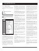
1 2 3 4 5
--- --- --- --- ---
6 7 8 9 10
--- --- --- --- ---
Min Vent. Relay Assignment
Set the status of each relay: select “2. “ if
the relay is used in minimum ventilation or
select “- - -” if it is not.
Relays 21-36 correspond to relays 1-16
of the external relay panel.
4.8.3. Variable Output Assignment
Two variable outputs can be used to provide
variable-speed ventilation. If they are used,
assign each of them to proper fan stages.
Select:1.
Current Conditions (Main Menu)
Setup *
Relays
Variables**
* A password may be required to access this menu.
** Accessible if variable outputs are enabled (sec. 4.5).
Fan Variable Assignment
Fan Stage 1 Variable 1 Var
Variable 2 Var
Fan Stage 2 Variable 1 On
Variable 2 Off
Set the output status separately for each 2.
fan stage in use:
Var — The variable fan output is assigned to
the fan stage and operates in variable mode:
when the stage starts, the variable fan starts
running at its minimum intensity. The fan
intensity gradually increases as the room
temperature increases.
On — The variable fan output is assigned to
the fan stage and operates in on/off mode:
the fan runs at 100% when the fan stage is
on and stops when the stage is off.
Off — The variable output is not assigned.
If the last fan stage uses a variable
output, the output must use the on/off
operating mode. Do not set the operat-
ing mode of the last fan stage to the
variable mode.
Tunnel 1-2 / inlet 1-2 / natural curtains 1-2 —
Relays 7-8 and relays 15-20 have specially
been designed for the connection of actua-
tors. When actuators are connected to these
relays, their open and close relays can never
be activated at the same time.
Feeding output — Feeder relays are used to
stop fee ders whe n a fee der run time alarm oc -
curs. These normally closed relays open when
the alarm condition is detected. *Accessible if
the feeder alarm condition is enabled (sec. 12.3).
Backup relay — The backup relay box relay is
a normally closed relay which opens in case
of a power failure.
Shutoff fans in natural ventilation — It is
possible to shutoff some fan output when
the controller enters in natural ventilation
(on/off fans and variable fans). Refer to the
natural ventilation section of this manual to
get further information about this feature.
Heating stages 1-3 & Hi Fire 1-3 (opt.);
Misting output;
Soaking output;
Kool-Cel® output;
Clock outputs 1-2;
Stir fan output;
Light output.
Worksheet showing default relay assign-
ment and empty templates are available
the end of this manual.
4.8.2. Assigning Min. Vent. Relays
This procedure shows how to assign on/off
relays to minimum ventilation cycles. Cho-
sen relays will switch during the “On Time”
portion of minimum ventilation cycles. Refer
to section 6.1 for further information about
minimum ventilation cycles.
Select:1.
Current Conditions (Main Menu)
Min. Vent.
MinV Relays*
* Accessible if the “Minimum Ventilation Relay status”
option is enabled in section 6.1.2. A password may also
be required to access this menu (section 4.2).