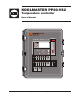
KOOLMASTER PP20-VS2 Temperature controller User’s Manual PP-20 VS2 Alarm Clean Mode Light Stir Fan Tunnel 2 - Open Tunnel 2 - Close Tunnel 1 - Open Tunnel 1 - Close Curtain 2 - Open Curtain 2 - Close Curtain 1 - Open Curtain 1 - Close Inlet 2 - Open Inlet 2 - Close Inlet 1 - Open Inlet 1 - Close Stage 12 Stage 11 Stage 10 Stage 9 Stage 8 Stage 7 Stage 6 Stage 5 Mist Soaking Stage 4 Stage 3 Kool-Cel ® Stage 2 Stage 1 01 02 03 04 05 06 0-10V #1 Min. Vent.
KOOLMASTER PP20-VS2 WARNINGS The warranty can be void if this product is used in a manner not specified by the manufacturer. Every effort has been made to ensure that this manual is complete, accurate and upto-date. The information contained in it is however subject to change without notice due to further developments. 2 KOOLMASTER PP20-VS2 rev.
KOOLMASTER PP20-VS2 TABLE OF CONTENTS 1. INTRODUCTION....................................................5 1.1. Precautions......................................................5 1.2. Symbols of the Manual......................................5 1.3. Controller’s Overview........................................5 1.4. Main Features...................................................6 2. MOUNTING INSTRUCTIONS...................................6 2.1. Installing the Controller on the Wall.....................
KOOLMASTER PP20-VS2 9. CLOCK OUTPUTS . .............................................36 10. RH COMPENSATION...........................................37 11. SOAKING...........................................................38 12. ALARMS............................................................39 12.1. Alarm Log......................................................39 12.2. Alarm Conditions............................................39 12.3. Alarm Settings..............................................
KOOLMASTER PP20-VS2 1. INTRODUCTION 1.1. 1.2. Precautions WARNING: Read and save these instructions! Safety may be jeopardized if the equipment is used in a manner not specified by the manufacturer. Carefully read and keep the following instructions for future reference. Controller’s Overview The KOOLMASTER PP20-VS2 is an electronic device used for environmental control in livestock buildings. It combines sidewall, natural and tunnel ventilation into one powerful system. High Voltage.
KOOLMASTER PP20-VS2 1.4. Main Features Very large LCD display: A large LCD screen provides an efficient interface for displaying, monitoring and adjusting the parameters. 3 Controller programs: The controller allows using 3 different programs to control the room temperature. It is thus possible to activate a specific program, that uses particular temperature settings, in accordance with the animal age for instance.
KOOLMASTER PP20-VS2 2.2.2. Alarm Connection There are two types of alarms on the market. One type activates when current is cut off at its input; the other type of alarm activates when current is supplied at its input. For an alarm of the first type, use the NC terminal as shown on the wiring diagram. For an alarm of the second type, use the NO terminal. 2.2.3. Sensor Inputs Sensors operate at low voltage and are isolated from the supply.
KOOLMASTER PP20-VS2 3.2. Parameter Adjustment Use the navigation buttons to select the desired parameter on the main screen. A parameter that can be modified blinks when it is selected; non-blinking parameters cannot be changed. 3.3. 3.4. LED Meaning LED MEANING CLEAN MODE Solid LED: Clean mode is active. ALARM Solid LED: An alarm condition is active. A corrective action is required. Flashing LED: An alarm condition occurred but no longer exists.
KOOLMASTER PP20-VS2 4. INSTALLATION SETUP 4.1. Setting the Time & Date 1. Select: Current Conditions (Main Menu) Time / Date Wed May 12 4.2. Password 4.2.1. Changing the Password 1. Select: The controller can use 3 password levels: User 1 password [1-1-1-1] This password provides access to temperature set points, minimum ventilation settings and to the animal count menu. If many password levels are used, the controller automatically selects this user level after 15 minutes of inactivity.
KOOLMASTER PP20-VS2 Program Settings Program Program Program Program 2 3 2 3 above above above above Show Settings : [ or ] Running Prog.: day: day: Out T: Out T: 10 20 50.0 75.0 Program 1 4.3.2. Copying & Pasting Programs 4.4. Measuring Units Use the copy-paste function to duplicate all parameter settings associated to a program onto another program. This avoids repeating the same programming sequence several times. 1. Select: Current Conditions (Main Menu) Setup * User 1.
KOOLMASTER PP20-VS2 4.5. Installation Setup The following section shows how to customize the controller for your particular application. It shows how to enable and set the outputs of your controller. Normally, this setup needs to be done only once. 4.5.1. Unshared Parameters The following parameters must be set separately for each controller program in use. 1. Select: Current Conditions (Main Menu) Setup * 2.
KOOLMASTER PP20-VS2 4.5.2. Shared Parameters The following parameters must be set only once since they are common to all controller programs. 1. Select: Current Conditions (Main Menu) Setup * User Installation * A password may be required to access this menu. Hint: use the right and left arrow keys to move up and down through the display by pages. Installation [...
KOOLMASTER PP20-VS2 Installation Use Age? Use Temperature Curve? Use Min Speed Curves? Use ON Time Curve? Out T° Comp. On Bdw 1&2 Number of Programs Switch Program by Age Switch Program by OutT Use Password? Use Password Level? Clear Alarm Log? Digit Display Clear Relay Assign.
KOOLMASTER PP20-VS2 4.6. RH Compensation Setup The controller offers different ways to compensate for high and low relative humidity (RH) levels in the barn. This section shows how to enable the desired RH compensation functions. Refer to chapter 10 of this manual to get more information about each of these compensation methods. 1. Select: Current Conditions (Main Menu) Setup * User RH Compens** * A password may be required to access this menu. ** Accessible if a humidity sensor is enabled (sec. 4.7.1) 2.
KOOLMASTER PP20-VS2 4.7.2. Probe & Water Meter Calibration You can slightly adjust the reading of each probe input in order to obtain accurate and uniform readings from all probes. In addition, if a water meter is used, you must calibrate its water flow rate. 1. Select: Current Conditions (Main Menu) Setup * User Prb Calib * A password may be required to access this menu. The following parameters are common to all programs of the controller.
KOOLMASTER PP20-VS2 Tunnel 1-2 / inlet 1-2 / natural curtains 1-2 — Relays 7-8 and relays 15-20 have specially been designed for the connection of actuators. When actuators are connected to these relays, their open and close relays can never be activated at the same time. Feeding output — Feeder relays are used to stop feeders when a feeder run time alarm occurs. These normally closed relays open when the alarm condition is detected. *Accessible if the feeder alarm condition is enabled (sec. 12.3).
KOOLMASTER PP20-VS2 4.9. Clean Mode The clean mode is used to interrupt regular operations of the controller when the room is empty. When this mode is enabled, the controller closes all tunnel doors and curtains and then only provides a minimum level of heat and ventilation (optional). If minimum ventilation is used in the clean mode, all inlets will open to their respective minimum ventilation position; otherwise they remain closed.
KOOLMASTER PP20-VS2 5. TEMPERATURE SETTINGS The set point is a target temperature in the room. The activation of most outputs of the controller is based on this reference temperature. Outside set point — The controller can adjust the moving speed of natural ventilation curtains as a function of outside temperature. When this function is used, the controller refers to the outside temperature set point to control the moving speed. Set the outside temperature to the desired value.
KOOLMASTER PP20-VS2 5.2.3. Modifying Curve Points 6. VENTILATION & COOLING 6.1.2. Min Ventilation Settings You can adjust the temperature set point associated to all curve points while the curve is running. 6.1. 1. Select: 1. Select: Definition: Minimum ventilation cycles are activated when the average room temperature is below the start temperature of fan stage 1.
KOOLMASTER PP20-VS2 Relay status — Set the relay status to “On” if some On/Off relays need to be activated during the “On Time” portion of minimum ventilation cycles. Refer to section 4.8.2 to assign On/ Off fan relays. Minimum ventilation timer — Set the timer that is used by the on/off fan outputs in minimum ventilation. The timer is composed of an “On Time” and “Cycle Time” . Note that the “Cycle Time” includes the “On Time”, it must thus be longer than the “On Time”.
KOOLMASTER PP20-VS2 6.2.1.1. Operation of Fan Stages The controller has 12 fan stages which operate in a sequence to increase the level of ventilation as the room temperature increases. Each stage can activate two variable outputs, on/off outputs, and a combination of timer relays for cooling purposes. A fan stage is activated when the room temperature reaches its start temperature and is disabled when the room temperature decreases to its stop temperature.
KOOLMASTER PP20-VS2 6.2.1.3. Outside Temperature Compensation Stage 1 and 2 bandwidths can be adjusted automatically as a function of outdoor temperature compensation. As the outside temperature decreases, stages 1 and 2 bandwidths increase gradually to compensate for the change. The user specifies the bandwidth used in summer as well as the bandwidth used in winter for both variable outputs of stages 1 and 2. The bandwidths can be adjusted from 1 to 10°F (0.6 to 5.6°C).
KOOLMASTER PP20-VS2 Timer — If timer-based relays are assigned to some fan stages (sec. 4.8), set the “On Time” and the “Off Time” of each timer-based relay. On and Off Times can be adjusted from 0 to 99 minutes in increments of 15 seconds. 6.2.2.2. Changes Seasonal Temperature If the outside temperature compensation on the bandwidths of stages 1 and 2 is used, you must specify at what outdoor temperature winter and summer start. 1. Select: Current Conditions (Main Menu) Start/Stop* 6.2.3.
KOOLMASTER PP20-VS2 6.3. Natural Ventilation Curtains 6.3.1. Principle of Operation The controller can control two natural ventilation curtains. To operate these curtains, the controller refers to the average temperature reading of their assigned temperature probes (see sec. 4.7.3). The controller enters in natural ventilation when the average temperature of the probes that are assigned to a curtain reaches the Initial Opening Temperature of the curtain.
2. If the tunnel door is used in natural vent.: When the room temperature falls below the natural ventilation’s start temperature [A], the tunnel door and natural ventilation curtain open during the “Continuous Open” delay. When this delay has elapsed, both outputs operate according to the natural ventilation timer [B]. 6.3.3. Natural Ventilation Settings 1. Select: Current Conditions (Main Menu) 1st tunnel stage Temperature falls 1. If the tunnel door is not used in natural vent.
KOOLMASTER PP20-VS2 6.3.4. Curtain Compensation 6.3.5. Stopping Fans in Natural Vent. The controller can slightly adjust opening of the curtains as a function of outside temperature: as the outside temperature increases, the controller increases the opening time of the curtains. As a result, curtains open faster when the outside temperature gets warm. Likewise, when the outside temperature gets cold the controller increases the closing time of the curtains. This compensation is optional.
KOOLMASTER PP20-VS2 6.4. Tunnel Doors The controller can control 2 tunnel doors as a function of room temperature. Beginning of tunnel ventilation: The activation of tunnel ventilation is linked with the activation of a user-defined fan stage: when the start temperature of that chosen fan stage is reached, the tunnel door opens during the opening time or reaches the position (in %) that is associated with that stage. The activation of every consecutive fan stages causes the tunnel door to open further.
KOOLMASTER PP20-VS2 6.5. Air Inlets Inlet Opening 6.5.1. Principle of Operation The controller can control the opening of 2 air inlets: the opening of the first inlet can either be defined by a potentiometer or with a timer; the second air inlet can only operate with a timer. Set the operating mode of the first air inlet in the Installation Setup (sec. 4.5). When using inlets, the user has to associate an inlet opening with the start-up of each fan stage.
KOOLMASTER PP20-VS2 Inlet 1 Settings Inlet 2 Auto Reset Calib Position 0 % Hysteresis +/3 % Temp Compensation 0 %/° Mode Manual Manual Mode Open/Off/Close Test Mode 72.3 °F Min Fan Speed 45 % Openings Closed 0 % Min. Vent. 5 % Stage 1 10 % Stage 1 Max 15 % Stage 2 20 % Stage 3 30 % Stage 4 40 % Stage 5 50 % Stage 6 60 % Stage 7 70 % Stage 8 80 % Over Opening settings Opening 100 % Bandwidth 5.
KOOLMASTER PP20-VS2 6.5.4. Inlet Calibration 1. Select: Current Conditions (Main Menu) Inlets* Auto-Reset* * Accessible if at least one timer-based inlet is enabled in the Installation Setup (section 4.5) and if this the manual mode status of this inlet is set to “Auto” in section 6.5.2. In addition, a password may be required to access this menu. The following parameters are common to all programs.
KOOLMASTER PP20-VS2 Opening — This is the current opening of the air inlet. This opening can be changed when the manual mode is enabled above. Temperature Compensation — The temperature compensation is expressed as a percentage per degree difference between the ambient temperature and the average reading of the inlet’s probes. For each degree above or below the average temperature, the inlet will open or close by the compensation value.
KOOLMASTER PP20-VS2 6.8. Misting Output Current Conditions (Main Menu) The controller can control one misting output. When the room temperature reaches the start temperature of the output, mist units are activated and run in timer mode according to their minimum timer (Min On Time & Min Off Time). Then, as temperature rises, a gradual transition is made from the minimum timer towards the maximum timer (Max On Time & Max Off Time).
KOOLMASTER PP20-VS2 1. Select: Current Conditions (Main Menu) Start/Stop* Stir Fan Output Stir Fan** * A password may be required to access this menu. Stir Fans in Hot Temperature Conditions On ** Accessible if the stir fan output is enabled in the Installation Setup (section 4.5). Stir Fan Settings Hot Temperature Yes Cold Temperature Yes Probe Differential Yes Hot Start Temperature 80.0 Hot Stop Temperature 79.5 Cold Start Temperature 70.0 Cold Stop Temperature 70.5 Probe Differential 5.
KOOLMASTER PP20-VS2 7. HEATING 7.1. Current Conditions (Main Menu) Heating Stages Start/Stop* The controller can control up to 6 independent heating outputs. Each heating output operates according to its start and stop temperature. Refer to section 4.5 to enable heating outputs. Heaters *A password may be required to access this menu. Heaters Start / Stop Heater Lo Lo Hi Hi Heater Reference Temperature: Start/stop temperatures are related to the set point.
KOOLMASTER PP20-VS2 0-10V Output #X Heat Lamp Mode Automatic Current Output 0 % Start Temperature 70.6 °F Minimum 40 Maximum 100 Max Output at 68.6 °F Stop at 71.1 °F Stop at Day Off day 7.3. Heat Mats (0-10V) 2. Set the following parameters: The controller has two 0-10V outputs that can either be used to control heat lamps, heat mats, inlets or fans. To operate these outputs, the controller refers to the average temperature reading of their assigned temperature probes (see sec. 4.7.3).
KOOLMASTER PP20-VS2 8. LIGHTS 9. CLOCK OUTPUTS The controller can control one light output. The lights turn on when the “On Time” of a light cycle is reached and turn off at the “Off Time”. In all, you can program up to 5 daily light cycles. Refer to section 4.5 to enable the desired number of cycles. The controller has 2 outputs to control various devices using the real-time clock. These clock output can use up to 12 timer cycles. 1. Select: 1.
KOOLMASTER PP20-VS2 10. RH COMPENSATION Fan Speed RH Comp. on the Fan Speed The controller offers different way to compensate for high/low relative humidity (RH) levels in the room. All compensation functions are explained below. Compensated speed 1. High RH Comp. on Fan Speed: The controller can compensate for high RH levels by increasing the speed of variablespeed fan outputs.
KOOLMASTER PP20-VS2 RH Settings 1. Select: Current Conditions (Main Menu) RH Comp* • Variable-Speed Fan Compensation * Accessible if at least one RH compensation function is enabled in section 4.6. In addition, a password may be required to access this menu (section 4.2). RH Compensation RH Set Point 65 % Min Vent.
KOOLMASTER PP20-VS2 12. ALARMS When an alarm occurs, the controller lights up the alarm pilot light, displays letters “AL” on the LED display, and post the alarm condition into the alarm log menu. Some userdefined alarm conditions may also activate the alarm relay. The table on the right gives a list of all possible alarm conditions. Refer to section 12.3 to specify which of these alarm conditions must activate the alarm relay. Another alarm situation occurs when power to the controller fails.
KOOLMASTER PP20-VS2 Water Spill Alarm: A water spill alarm sets off when the consumption of a water meter exceeds its respective consumption limit. This limit can be adjusted from 0 to 10,000 gallons or liters per 15 minutes. 12.3. Alarm Settings 1. Select: Current Conditions (Main Menu) Water Consumption Alarms: When the percent difference in water consumption between the last 24-hour period and the previous 24-hour period is greater than a given maximum value, an alarm is set off.
KOOLMASTER PP20-VS2 Feeder monitoring — Select “Yes” if you want the controller to monitor the run time of feeding inputs. If this alarm condition is enabled, set the maximum run time of each feeder (in minutes). Refer to section 4.8 to assign the relay that must open in case of a run time alarm. *Accessible if feeders are enabled (section 4.5). T° Probe Difference — Select “Yes” if you want the controller to sound an alarm if the 13.
KOOLMASTER PP20-VS2 13.3. Animal Age & Count Animal age: Some parameters of the controller can automatically change over time as the animals grow up (curves, programs & tunnel door). Using age-based parameters is optional, refer to section 4.5 to enable or disable the animal age function. Animal count (Current count / mortality / culled / marketed): At the beginning of a group, the user must specify the initial number of animals.
KOOLMASTER PP20-VS2 14. TECHNICAL SPECIFICATIONS 15.3. Configuration Transfer 15. MEMORY CARD Configuration Files (*.cfg) 15.1. Principle of Operation Type KOOLMASTER PP20VS2 Main supply Fuse F1 4A, slow-blow Mains supply/frequency 85-250V, 50/60Hz 0-10V outputs 1-2 0-10Vdc, 30mA source max. Precision on 0-10V outputs ±1 % 14Vdc output 14 VDC ±10%, regulated, 250 mA max. Variable outputs 1,2 230VAC, 10A Max, 1.5HP (230VAC) / 0.5HP (115VAC) Alarm contact 150 mA, 24 Vac or dc max.
KOOLMASTER PP20-VS2 15.3.2. Saving a Configuration on the Card 15.4. Firmware Update The following procedure shows how to save your controller’s configuration into the memory card. This will create a configuration file (*.cfg) on the card. The controller’s firmware contains instructions and data responsible for controlling the controller. When a new firmware version is available, you can install it in your controller by downloading a firmware file (*.fir) from the card.
KOOLMASTER PP20-VS2 16. INDEX A Age.
KOOLMASTER PP20-VS2 Memory card Erasing the card 44 Transfer process 43 Menu selectors 7 Minimum ventilation Min speed curve. See Curves Night ventilation Activation 16 Settings 19 On Time curve. See Curves On Time ramping.
M 890-00527 rev.00 REV.