
Installation Instructions


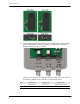


Table Of Contents

Synergize RF ILC Installation Instructions 9
5. Refer to the wiring diagram when routing the desired load wires through the
appropriate conduit. Remove approximately.28-.31 inches (7.0-
8.0 mm) of insulation from the end of each wire, so as to make a good
connection without leaving any copper exposed.
N
OTE
ILC device tamper detection requires that the input power and any connected
relay ports use the same electric service phase. Failure to connect power and
loads to the same phase may result in failure to report a load control event
and/or erroneous tamper events. The selected ILC service phase may use a
208 VAC - 277 VAC connection.