Final Assembly of SCG DCU All SCG DCU Product Family(s) 501-9975VERLT1R1-SCG 501-9975VERST1R1-SCG 501-9975ATTLT1R1-SCG 501-9975ATTST1R1-SCG Product P/N(s) this Document Covers REVISIONS Rev. A B C D Description of Change(s) Initial Release Add: 11700-CELL-SOL-SCG, redesigned to use compact enclosure. Remove: All references to Ascendant and full size enclosure. Remove: Auxiliary FCC label. Add: Reference to Test Procedure 465-11700-02-PTI for security switch hardware.
Final Assembly of SCG DCU 1.0 Scope: 1.1 This procedure details the final assembly process for all SoCal Gas (SCG) DCUs. Section 4.1: Final assembly of plastic box (electronics package). Section 4.2: Installation of the enclosure cover. Section 4.3: Placement of product labels. 2.0 General Safety and Work Area Guidelines: 2.1 Eye protection shall be worn in the assembly area at all times. 2.
Final Assembly of SCG DCU 2.7 Table 1 provides a list of tools and materials which are required to perform this procedure. Materials called out here are in addition to those already included on the product bill of material (BOM). Quantity As Req’d 1 1 1 1 3.
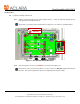
Final Assembly of SCG DCU 4.0 Procedure: 4.1 Complete assembly of plastic box. 4.1.1 Install (10) barbed printed circuit board (PCB) retainers. These are manually pushed into the holes provided in each PCB slide rail. Install ALL (10) retainers in the position shown in Figure 2, even if there is no PCB installed. 069-0080 (x10) Retainer Detail Figure 2: Install Barbed PCB Retainers 4.1.2 Place clear plastic box cover p/n 056-9975 over the top of the plastic box.
Final Assembly of SCG DCU 4.2 Assemble and install the DCU cover. 4.2.1 Install the strike plate (056-9975X-2) as shown in Figure 3. Using a clean cloth and Isopropyl Alcohol, clean the surface where the strike plate is to be installed. Orient fixture FIX-1X700-002 as shown, holding the corner of the fixture firmly into the inside corner of the enclosure cover. Remove the paper backing of the strike plate and place using the inside corner of the fixture as a guide.
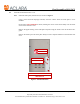
Final Assembly of SCG DCU 4.2.2 Add the Installation & Maintenance Record form with vinyl sheet protector to the inside of the enclosure cover as shown in Figure 4. Clean the inside surface of the enclosure cover with Isopropyl Alcohol to remove any oil or contaminants. Remove paper backing from the sheet protector. With the red zipper seal towards the top edge of the cover, center the sheet protector on the inside of the cover as shown and smooth down by hand. 4.2.
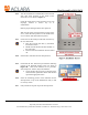
Final Assembly of SCG DCU 4.2.8 On the top left edge of the enclosure are (2) slots for mounting the cover; see Figure 5-I. Holding the cover as shown in Figure 5-II, place both tabs, on the covers edge, into the slots of the enclosure. With the tabs in both slots, the cover should slide about ¼” toward the bottom of the enclosure. Close the enclosure cover and observe that the tab and slot mate up as shown in Figure 5-III.
Final Assembly of SCG DCU 4.2.9 Connect the bonding jumper to the enclosure cover as shown in Figure 6. 069-3215LS 7/16" 35 in-lb 069-3201A Flat Washer 070-10700 069-3202A Bonding Jumper Split Washer Figure 6: Connect Bonding Jumper 4.2.10 Test security switch hardware per procedure 465-11700-02-PTI. Upon successful completion of test, the operator shall place their stamp on a clearly visible location of the switch bracket.
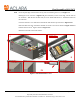
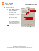
Final Assembly of SCG DCU 4.3 Placement of product labels. 4.3.1 Refer to Figure 7 for installation of the DCU FCC/IC ID label. FIX-1X700-001 Fixture Clean the surface of the enclosure with Isopropyl Alcohol. Place the fixture in the orientation shown. Align the fixture square with the top-left corner of the enclosure cover using the guide rail and the top edge of the fixture as shown. Remove the paper from the adhesive back of the label.
Final Assembly of SCG DCU 4.3.2 Refer to Figure 8 for installation of the Hazard label. FIX-1X700-001 Fixture Clean the surface of the enclosure with Isopropyl Alcohol. Place the fixture in the orientation shown. Set the fixtures guide rail to the right edge of the enclosure cover, then slide the fixture up until it stops against the upper screw used to hold the cover closed. Remove the paper from the adhesive back of the label.
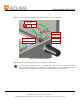
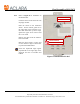
Final Assembly of SCG DCU 4.3.3 Refer to Figure 9 for installation of the info label. Clean the surface of the enclosure with Isopropyl Alcohol. There is a unique info label for every model DCU. The Model# on the label must match the item number on the work order. Refer to the current work order or assembly print to identify the label part number. Place the fixture in the orientation shown.
Final Assembly of SCG DCU 4.4 Intentionally left blank. End of Document Document No.: AP-1X700-003-MAD Rev.