
User's Manual
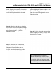


Table Of Contents
- Table of Contents
- 471-2000.pdf
- 471-2001.pdf
- 471-2002.pdf
- 471-2003.pdf
- 471-2004.pdf
- 471-2005.pdf
- 471-2006.pdf
- 471-2007.pdf
- 471-2008.pdf
- 471-2009.pdf
- 471-2010.pdf
- 471-2011.pdf
- 471-2012.pdf
- 471-2013.pdf
- 471-2014.pdf
- 471-2015.pdf
- 471-2016.pdf
- 471-2017.pdf
- 471-2018.pdf
- 471-2019.pdf
- 471-2020.pdf
- 471-2021.pdf
- 471-2022.pdf
- 471-2023.pdf
- 471-2026.pdf
- 471-2027.pdf
- 471-2028.pdf
- 471-2029.pdf
- 471-2030.pdf
- 471-2031.pdf
- 471-2032.pdf
- 471-2033.pdf
- 471-2034.pdf
- 471-2035.pdf
- 471-2036.pdf
- 471-2037.pdf
- 471-2038.pdf
- 471-2040.pdf
- 471-2041.pdf
- 471-2042.pdf
- 471-2043.pdf
- 471-2044.pdf
- 471-2045.pdf
- 471-2046.pdf
- 471-2047.pdf
- 471-2051.pdf
- 471-2052.pdf
- 471-2053.pdf
- 471-2054.pdf

MTU Instruction
for Dresser Gas Meters with Vertical Mechanical Index
Step 4 – If the index box and/or base
plate mounting screws were difficult to
remove, the threads in the meter head
may need to be cleaned out before
installing the new hardware that will retain
the index base plate, the pulser and the
index box. Use the blind-hole taps to
carefully clean the threads of the index
box and base plate mounting holes.
CAUTION!
The index base plate
mounting holes use a 5/16-18
thread. The index box
mounting holes use a #12-24
thread. Be sure to use the
proper tap for each hole.
Using the wrong tap will result
in damage to the meter head.
After using the tap, blow out the holes
with compressed (canned) air.
Step 5 – Place the index base plate onto
the instrument drive of the meter. Align
the index base plate with the index plate
mounting holes on the instrument drive so
that the large opening in the base plate is
centered over the drive mechanism.
Step 6 – Break out the tab for either the
front or rear wire exit on the bottom edge
of the pulser body, depending on how you
plan to mount the MTU. (See the
illustration below.)
Step 7 – Assemble the couplers and
shaft to the pulser body as shown in the
illustration below. Ensure that the
magnet is mounted on the Tall Coupler,
and that the retaining shaft is securely
snapped into both the Tall Coupler and
the 2-Pin Drive Disk.
Page 127