
User's Manual
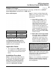


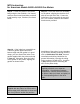
Table Of Contents
- Table of Contents
- 471-2000.pdf
- 471-2001.pdf
- 471-2002.pdf
- 471-2003.pdf
- 471-2004.pdf
- 471-2005.pdf
- 471-2006.pdf
- 471-2007.pdf
- 471-2008.pdf
- 471-2009.pdf
- 471-2010.pdf
- 471-2011.pdf
- 471-2012.pdf
- 471-2013.pdf
- 471-2014.pdf
- 471-2015.pdf
- 471-2016.pdf
- 471-2017.pdf
- 471-2018.pdf
- 471-2019.pdf
- 471-2020.pdf
- 471-2021.pdf
- 471-2022.pdf
- 471-2023.pdf
- 471-2026.pdf
- 471-2027.pdf
- 471-2028.pdf
- 471-2029.pdf
- 471-2030.pdf
- 471-2031.pdf
- 471-2032.pdf
- 471-2033.pdf
- 471-2034.pdf
- 471-2035.pdf
- 471-2036.pdf
- 471-2037.pdf
- 471-2038.pdf
- 471-2040.pdf
- 471-2041.pdf
- 471-2042.pdf
- 471-2043.pdf
- 471-2044.pdf
- 471-2045.pdf
- 471-2046.pdf
- 471-2047.pdf
- 471-2051.pdf
- 471-2052.pdf
- 471-2053.pdf
- 471-2054.pdf

MTU Instruction
for American Model AL800-AL5000 Gas Meters
Tools Required
• Screwdriver, #2 Phillips
• Screwdriver, 3/8” slotted (flat-
blade)
• 7/16” box wrench
• 18-18 blind-hole (bottoming) tap
and mating size T-handle
• 12-24 blind-hole (bottoming) tap
and mating size T-handle
• Canned compressed air
Also see Publication 471-2000, General
Installation and Wiring Guidelines for a
complete list of recommended tools and
supplies for MTU Installation.
Installation Procedure
There are two parts to this procedure.
First, the pulser must be mounted to the
meter. Once this is complete, you can
mount the MTU remotely or directly on
the pulser using the adapter provided. If
you are mounting the MTU on the pulser,
it can be mounted at either the front or
back of the meter.
Step 1 – If necessary, remove tamper
seals from any of the 4 screws that
secure the index base plate and the two
screws that secure the index box to the
base plate.
Note: If the index base plate has integral
security towers like the one on the left
below, it must be replaced with the flat
style index base plate like the one shown
on the right.
Step 2- Loosen and remove the four
screws securing the index base plate
assembly to the meter. You may discard
these screws as they will not be re-used.
Remove the index box and base plate
assembly from the top of the meter.
Step 3 – Disassemble the index box from
the base plate by removing the two
screws that secure the index box to the
base plate. You may discard these
screws as they will not be re-used.
Step 4 – If the index box and/or base
plate mounting screws were difficult to
remove, the threads in the meter head
may need to be cleaned out before
installing the new hardware that will retain
the index base plate, the pulser and the
index box. Use the blind-hole taps to
carefully clean the threads of the index
box and base plate mounting holes.
CAUTION!
The index base plate
mounting holes use a #18-18
thread. The index box
mounting holes use a #12-24
thread. Be sure to use the
proper tap for each hole.
Using the wrong tap will result
in damage to the meter head.
Page 108