
Installation Instructions
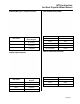
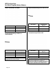
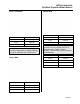
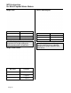
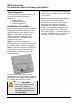
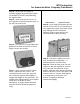

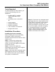
Table Of Contents
- Table of Contents
- 471-2000.pdf
- 471-2001.pdf
- 471-2002.pdf
- 471-2003.pdf
- 471-2004.pdf
- 471-2005.pdf
- 471-2006.pdf
- 471-2007.pdf
- 471-2008.pdf
- 471-2009.pdf
- 471-2010.pdf
- 471-2011.pdf
- 471-2012.pdf
- 471-2013.pdf
- 471-2014.pdf
- 471-2015.pdf
- 471-2016.pdf
- 471-2017.pdf
- 471-2018.pdf
- 471-2019.pdf
- 471-2020.pdf
- 471-2021.pdf
- 471-2022.pdf
- 471-2023.pdf
- 471-2026.pdf
- 471-2027.pdf
- 471-2028.pdf
- 471-2029.pdf
- 471-2030.pdf
- 471-2031.pdf
- 471-2032.pdf
- 471-2033.pdf
- 471-2034.pdf
- 471-2035.pdf
- 471-2036.pdf
- 471-2037.pdf
- 471-2038.pdf
- 471-2040.pdf
- 471-2041.pdf
- 471-2042.pdf
- 471-2043.pdf
- 471-2044.pdf
- 471-2045.pdf
- 471-2046.pdf
- 471-2047.pdf
- 471-2051.pdf
- 471-2052.pdf
- 471-2053.pdf
- 471-2054.pdf

MTU Instruction
for American Meter Company Gas Meters
Step 4 – Check that the register is
properly engaged by rotating the coupler
on the back of the MTU and observing
the register dials.
Step 5 – Next, Insert the two ¼-20 x 1
1/4” machine screws through the holes on
the MTU as shown here.
Step 6– Turn the MTU over and place the
gasket on the back of the MTU so that it
aligns over the two screws.
Step 7 – Next, position the MTU on the
meter. Tighten the two ¼-20 x 1 1/4”
mounting screws most of the way, and
then rotate the register dials slightly to
engage the wiggler on the gas meter. The
wiggler must engage with the rear coupler
on the MTU as shown in these
illustrations. (Coupler shown detached
from the MTU for illustration purposes
only.)
Half-foot Drive Quarter-foot Drive
Step 8 – Now, firmly hand tighten the two
screws to 12 to 15 in-lb. Be careful not to
over tighten the screws. Excessive torque
may damage the MTU enclosure.
Because of this, power tools are not
recommended for this procedure.
Step 9 - Check the coupling one more
time. It should have slight play — it
should not bind or turn too freely.
Step 10 - Place the new cover over the
register so that the top label or arrow is
on top and the vent holes are on the
bottom. Align the cover with the mounting
holes on the MTU, press it into place, and
insert the #10 x 1” screws. Hand tighten
to a torque not to exceed 3-5 inch-
pounds. The gasket should be
compressed slightly.
Page 27