
Installation Instructions

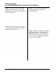
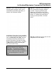
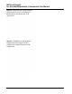
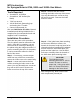
Table Of Contents
- Table of Contents
- 471-2000.pdf
- 471-2001.pdf
- 471-2002.pdf
- 471-2003.pdf
- 471-2004.pdf
- 471-2005.pdf
- 471-2006.pdf
- 471-2007.pdf
- 471-2008.pdf
- 471-2009.pdf
- 471-2010.pdf
- 471-2011.pdf
- 471-2012.pdf
- 471-2013.pdf
- 471-2014.pdf
- 471-2015.pdf
- 471-2016.pdf
- 471-2017.pdf
- 471-2018.pdf
- 471-2019.pdf
- 471-2020.pdf
- 471-2021.pdf
- 471-2022.pdf
- 471-2023.pdf
- 471-2026.pdf
- 471-2027.pdf
- 471-2028.pdf
- 471-2029.pdf
- 471-2030.pdf
- 471-2031.pdf
- 471-2032.pdf
- 471-2033.pdf
- 471-2034.pdf
- 471-2035.pdf
- 471-2036.pdf
- 471-2037.pdf
- 471-2038.pdf
- 471-2040.pdf
- 471-2041.pdf
- 471-2042.pdf
- 471-2043.pdf
- 471-2044.pdf
- 471-2045.pdf
- 471-2046.pdf
- 471-2047.pdf
- 471-2051.pdf
- 471-2052.pdf
- 471-2053.pdf
- 471-2054.pdf

MTU Instruction
for Rockwell/Equimeter Commercial Gas Meters
Step 10 – Next, mount the index cover
onto the pulser using the 5/16 -18 x 3”
slotted fillister head bolts provided, as
shown in the illustration below.
Installation of the pulser is now complete.
If you will be remotely mounting the MTU,
refer to Publication 471-2000, General
Installation and Wiring Guidelines for
general information covering the wiring
and mounting of STAR MTUs. Continue
to Step 11 if you will be mounting the
MTU to the pulser body.
NOTE: The pulser and MTU can be
supplied pre-wired or as separate
assemblies. If provided as separate
components, connect the three wires in
the pulser cable (red, black, and white) to
the corresponding wires in the MTU
cable.
Step 11 – Continue here to mount the
MTU to the pulser using the adaptor
provided. Begin by positioning the
adaptor on the back (or front) of the
pulser body and attach it using the two
#8-18 x ½” Phillips pan head thread
forming screws provided, as shown
below.
Step 12 – Bundle the excess wire into the
compartment on the adaptor.
Page 117